
Bonding structure, actuator device and liquid-jet head

a technology of actuator device and liquid-jet head, which is applied in the direction of electrical equipment, semiconductor devices, printing, etc., to achieve the effect of narrowing the width of the bonding pad

Inactive Publication Date: 2008-07-15
SEIKO EPSON CORP
View PDF13 Cites 2 Cited by
  • Summary
  • Abstract
  • Description
  • Claims
  • Application Information

AI Technical Summary

Benefits of technology

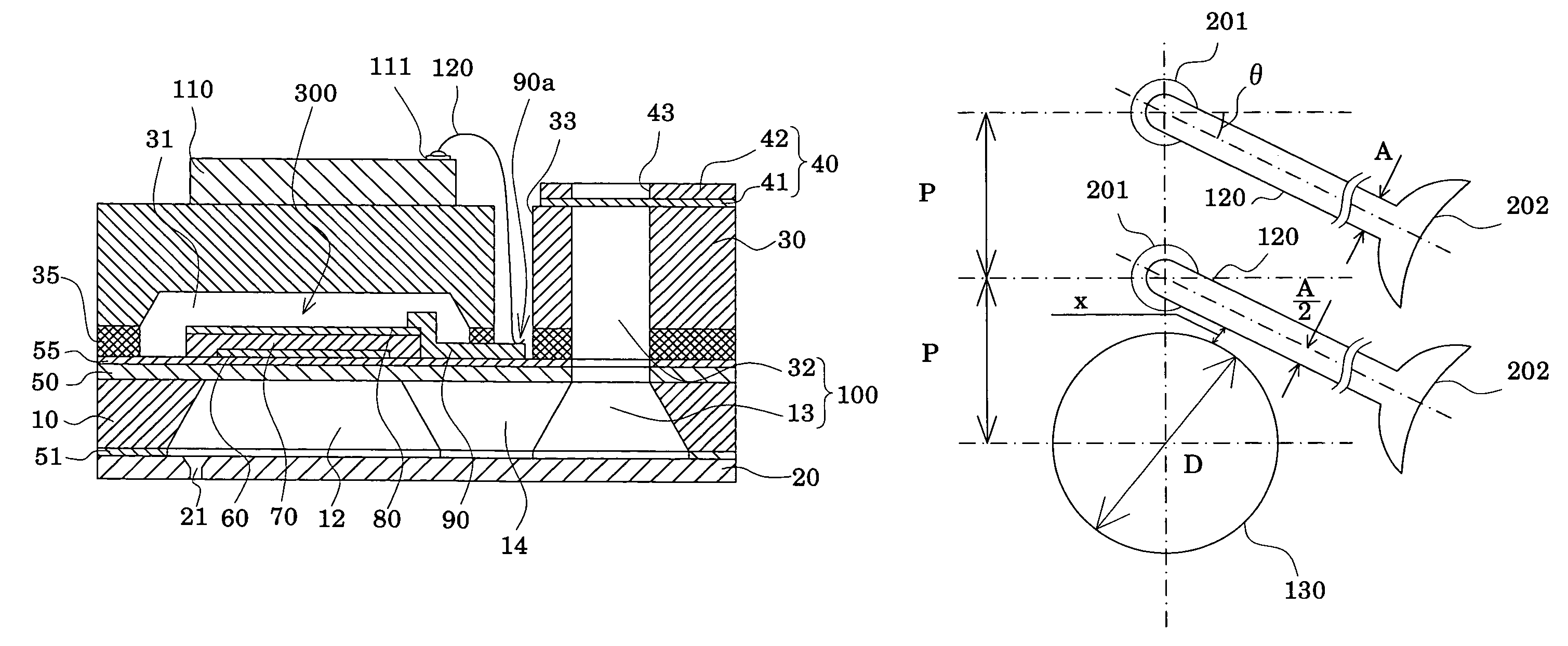
The present invention provides a bonding structure that can ensure high-density wiring for devices using bonding wires. The bonding structure includes a bonding pad connected to a terminal portion of a drive IC, and a plurality of bonding portions arranged on a straight line. The pitch of the bonding portions is set at XA+σ or more, where XA is the diameter of the bonding wires and σ is the variation for the bonding procedure. The bonding wires can be arranged in an inclined manner at an angle θ with respect to a direction perpendicular to the direction of arrangement of the bonding portions. The bonding structure can be used in an actuator device and a liquid-jet head. The use of the bonding structure can facilitate the arrangement of the bonding portions in an optimal status for high-density wiring.

Problems solved by technology

The above-described problems are true of not only liquid-jet heads such as ink-jet recording heads, but also devices having a bonding wire connecting structure using semiconductor elements such as LSI and IC.

Method used


Image

  • Bonding structure, actuator device and liquid-jet head
  • Bonding structure, actuator device and liquid-jet head
  • Bonding structure, actuator device and liquid-jet head

Examples


Embodiment Construction

[0034]The present invention will now be described in detail based on the embodiments offered below.

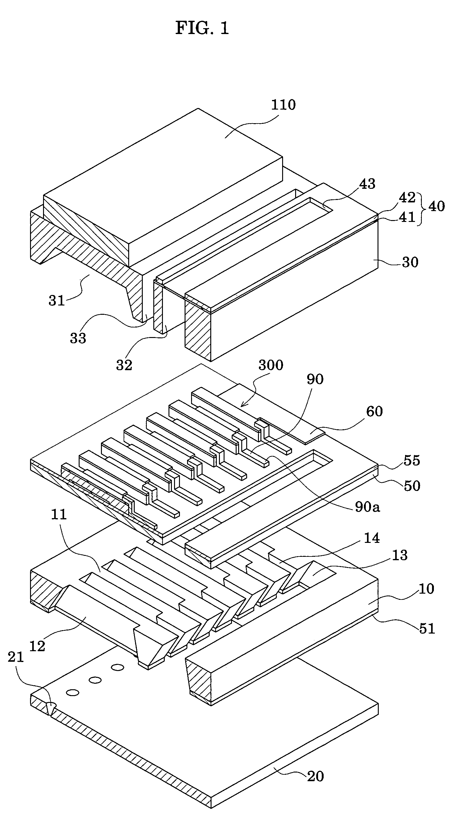
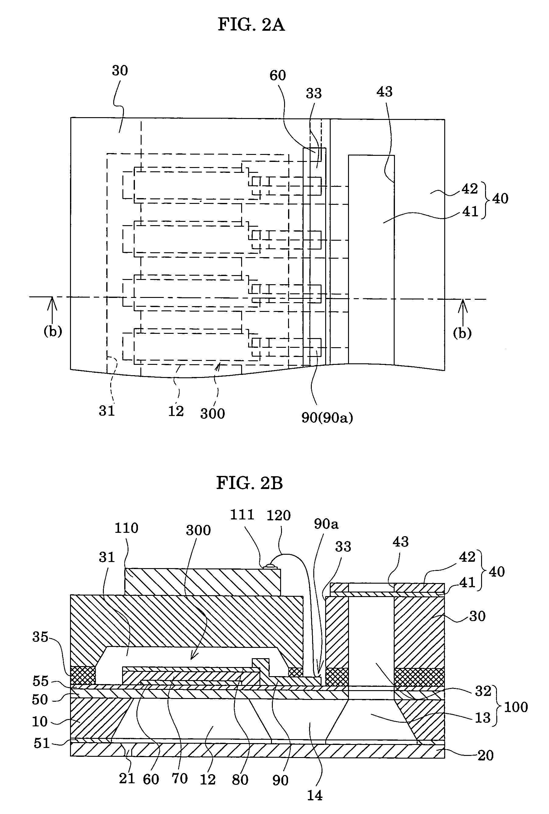
[0035]FIG. 1 is an exploded perspective view showing a liquid-jet head according to an embodiment of the present invention. FIG. 2(a) and FIG. 2(b) are a plan view and a sectional view, respectively, of the liquid-jet head in FIG. 1.

[0036]A passage-forming substrate 10 constituting the liquid-jet head, in the present-embodiment, consists of a single crystal silicon substrate. An elastic film 50, composed of silicon dioxide formed beforehand by thermal oxidation, is formed on one surface of the passage-forming substrate 10. In the passage-forming substrate 10, pressure generating chambers 12 partitioned by a plurality of compartment walls 11 are formed by anisotropic etching performed from the other surface of the passage-forming substrate 10. Longitudinally outwardly of the pressure generating chambers 12 arranged in a row, a communicating portion 13 is formed which communicates with a...


PUM


Abstract

A bonding structure including bonding wires having a diameter A, bonding pads to which the bonding wires are connected, and bonding portions which, as sites of connection, are arranged on a straight line, and wherein the pitch P of the bonding portions is set at XA+σ or more where 1.80≦X≦2.1, A is as defined above, and σ denotes a variation for the bonding procedure.

Description

BACKGROUND OF THE INVENTION[0001]1. Field of the Invention[0002]This invention relates to a bonding structure involving bonding wires connected to bonding pads. More particularly, the invention relates to the bonding structure which is preferred for application to an actuator device equipped with a vibration plate and a piezoelectric element, especially, for application to a liquid-jet head where a portion of a pressure generating chamber communicating with a nozzle orifice for ejecting ink droplets is constituted of a vibration plate, a piezoelectric element is formed on the surface of the vibration plate, and ink droplets are ejected by displacement of a piezoelectric layer.[0003]2. Description of the Related Art[0004]An actuator device equipped with a piezoelectric element displaced by application of a voltage is installed, for example, on a liquid-jet head for jetting liquid droplets. Known as such a liquid-jet head is, for example, an ink-jet recording head in which a portion o...

Claims


Application Information

Patent Timeline
Patent Type & Authority Patents(United States)
IPC IPC(8): B41J2/14
CPCB41J2/14233B41J2/1623H01L24/05H01L24/85B41J2/161H01L2224/04042B41J2002/14241B41J2002/14419B41J2002/14491H01L24/45H01L24/78H01L2224/05556H01L2224/05624H01L2224/05644H01L2224/45015H01L2224/45144H01L2224/48091H01L2224/48228H01L2224/48465H01L2224/78301H01L2224/85181H01L2924/01004H01L2924/01013H01L2924/01014H01L2924/01015H01L2924/01022H01L2924/01028H01L2924/01074H01L2924/01079H01L2924/01082H01L2924/09701H01L2924/20752H01L2224/48227H01L2924/12041H01L2224/48644H01L2924/01005H01L2924/01006H01L2924/01024H01L2924/01033H01L2224/48624H01L2924/00014H01L2924/00H01L2224/85205H01L24/48B41J2/045B41J2/16
Inventor OWAKI, HIROSHIGEMIYATA, YOSHINAO
Owner SEIKO EPSON CORP
Learn More