
Opposed path joint

a technology of opposing paths and paths, applied in the direction of yielding couplings, clutches, rotary machine parts, etc., can solve the problems of time-consuming assembly steps, which are performed manually, and achieve the effect of preventing the penetration of dirt into the join

Inactive Publication Date: 2008-07-08
SHAFT FORM ENG GMBH
View PDF26 Cites 15 Cited by
  • Summary
  • Abstract
  • Description
  • Claims
  • Application Information

AI Technical Summary

Benefits of technology

"The invention is about an opposed path joint for vehicles that can withstand high stress and is suitable for mass production. The joint has an outer hub with a single-piece closed ring design that can absorb high forces. The outer hub has outer grooves formed without cutting, which allows for high production precision. The joint is guided by cage centering surfaces in the inner surface of the outer hub, and the cage is introduced into the outer hub in a specific position and then rotated to cover the hub. The outer hub can be connected with a driving or driven component, and a sealing disk can be used to prevent dirt penetration and ensure lubrication. The invention also includes an accommodation part that surrounds the outer hub and can rotate with it. Overall, the invention provides an improved opposed path joint that is stronger, more efficient, and easier to install."

Problems solved by technology

This assembly step, which is performed manually, is time-consuming.

Method used


Image

  • Opposed path joint
  • Opposed path joint
  • Opposed path joint

Examples


Embodiment Construction

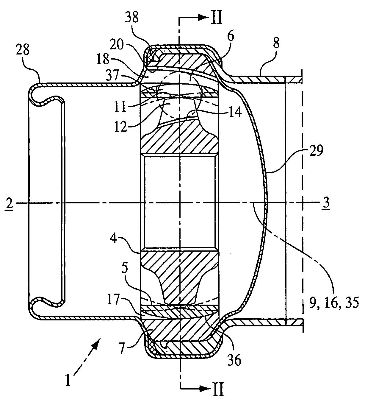
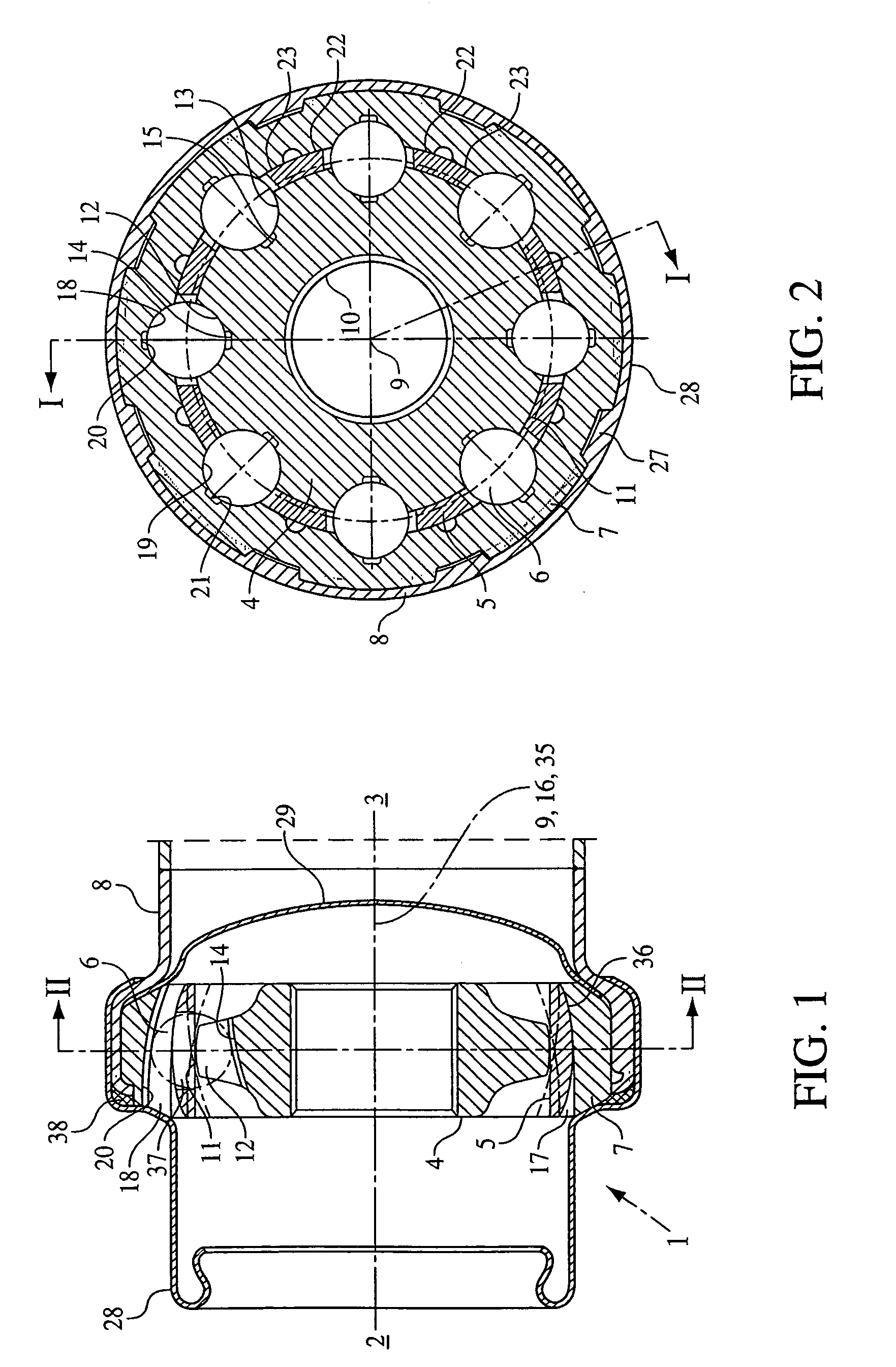
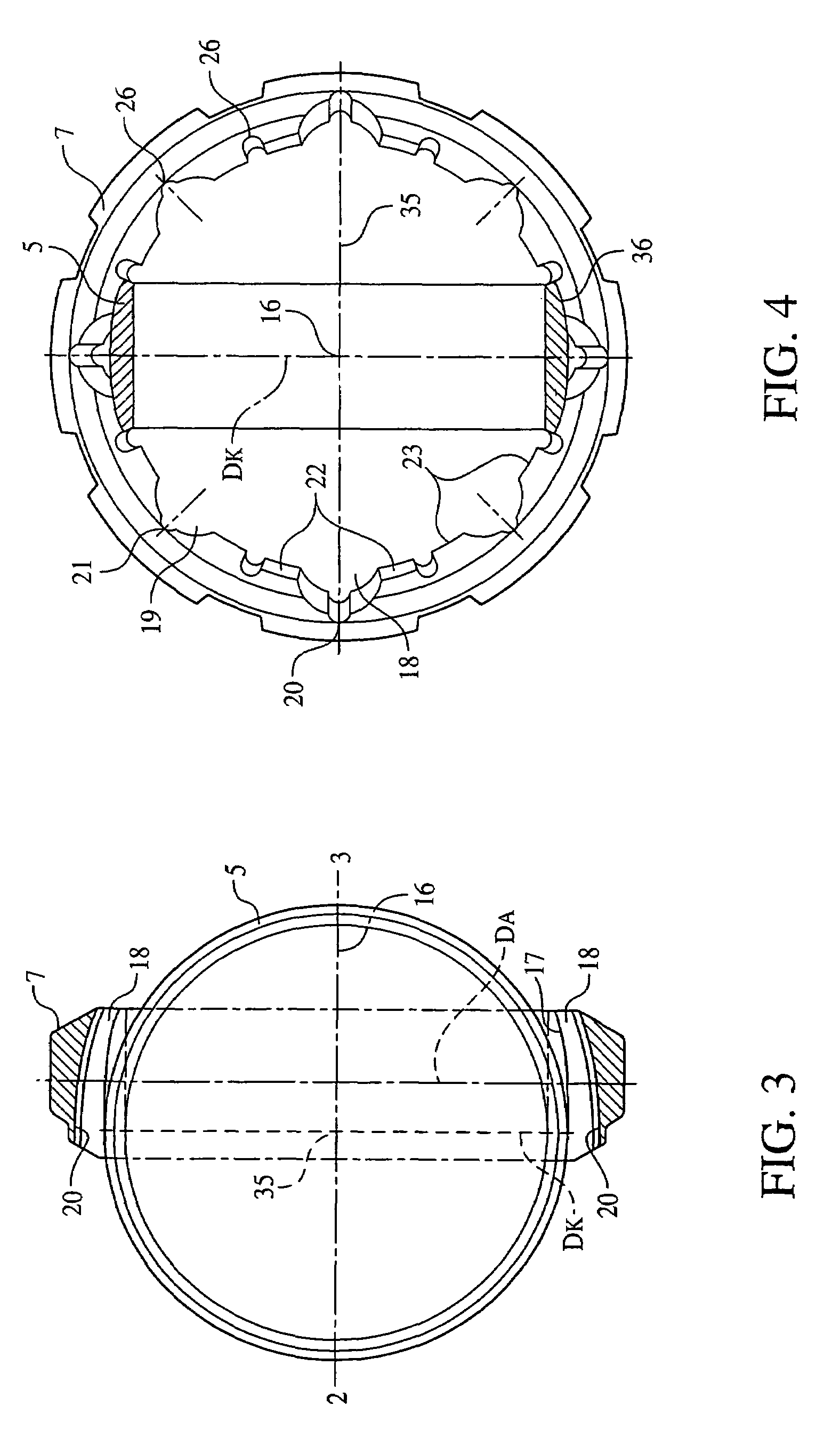
[0044]A first embodiment of an opposed path joint 1 is shown in FIG. 1 to 4. In FIG. 1, a drive-side end 2 and a power-take-off-side end 3 is indicated, whereby the designations “drive-side end” and “power-take-off-side end” were selected in the following description purely as an example, for a better differentiation of the two ends. Of course both ends 2, 3 are suitable for being connected with a driving component or a power take-off component.

[0045]From the inside to the outside, the opposing path joint 1 has an inner hub 4, a cage 5, in which balls 6 are guided, an outer hub 7, and an accommodation part 8.

[0046]The inner hub 4 is a ring-shaped component having a central inner hub axis 9 and a profiled inner surface 10 for a connection with a driving component or a driven component. The outer surface 11 of the inner hub 4 has several first inner grooves 12 and second inner grooves 13, arranged on the circumference, regularly and alternately distributed.

[0047]The first inner groove...


PUM


Abstract

An opposed path joint comprising an inner hub, which is provided with first inner grooves and second inner grooves, and comprising an outer hub, which is provided with first outer grooves and second outer grooves that respectively form a pair with the first and second inner grooves. The opposed path joint also comprises an annular cage, which is placed between the inner hub and the outer hub and which has a radial openings whose number corresponds to that of the groove pairs. Balls that engage inside the grooves are guided inside these radial openings. According to the invention, the outer hub of the opposed path joint is a single-piece closed ring, in which the outer grooves are formed without cutting. Alternatively, the outer hub has at least two elements that are located one behind the other on the outer hub axis and, together, center the cage.

Description

CROSS REFERENCE TO RELATED APPLICATIONS[0001]Applicants claim priority under 35 U.S.C. Å119 of German Application No. 102 09 933.2 filed on Mar. 7, 2002 and German Application No. 102 12 540.6 also filed on Mar. 7, 2002. Applicants also claim priority under 35 U.S.C. Å365 of PCT / EP03 / 02318 filed on Mar. 6, 2003. The international application under PCT article 21(2) was not published in English.BACKGROUND OF THE INVENTION[0002]1. Field of the Invention[0003]The invention relates to an opposed path joint that has a drive side and a power take-off side, having an inner hub, an outer hub, and a ring-shaped cage having a spherical outer surface, which cage is arranged between the inner hub and the outer hub and has several radial openings, in which balls are guided. The inner hub has an inner hub axis and an outer surface, in which first inner grooves and second inner grooves are arranged, alternately distributed about the inner hub axis. In this connection, the first inner grooves run f...

Claims


Application Information

Patent Timeline
Patent Type & Authority Patents(United States)
IPC IPC(8): F16D3/224F16D1/00F16D3/223F16D3/2237
CPCF16D3/223F16D3/2237F16D3/224F16D3/84F16D2003/22303Y10S464/906F16D2003/22316F16D2003/22326F16D2250/00F16D2300/12F16D2003/22306F16D2250/0023F16D3/20
Inventor JACOB, WERNERJACOB, MARTIN D.
Owner SHAFT FORM ENG GMBH
Learn More