
Variable-force payload ejecting system

a payload and variable force technology, applied in the field of ejecting items, can solve the problems of high shock acceleration load on the submunition, the ejecting system cannot compensate for variations, and the multiple target areas separated by some distance cannot be accommodated by a single air vehicle, so as to achieve the delivery of submunitions precisely, the effect of precision and accuracy

Inactive Publication Date: 2008-07-08
UNITED STATES OF AMERICA THE AS REPRESENTED BY THE SEC OF THE ARMY
View PDF41 Cites 7 Cited by
  • Summary
  • Abstract
  • Description
  • Claims
  • Application Information

AI Technical Summary

Benefits of technology

[0007]The result is a more precise delivery of the submunitions onto the intended targets. The precision and accuracy is particularly notable when the variable-force ejecting system is combined with an axial ejection technique.

Problems solved by technology

Such an ejecting system cannot compensate for variations in the velocity of the air vehicle, the height from which the item (submunition) is ejected or any other factors that can affect the precision placement of the submunitions in actual (battlefield) use.
Multiple target areas separated by some distance cannot be accommodated by a single air vehicle.
Finally, the radial ejection technique, in particular, leads to high shock and acceleration loads on the submunitions, since the ejecting system must break any restraining straps that hold the submunitions in place in the air vehicle before the submunitions can be separated from the air vehicle.

Method used


Image

  • Variable-force payload ejecting system
  • Variable-force payload ejecting system
  • Variable-force payload ejecting system

Examples


Embodiment Construction

[0015]Referring now to the drawing wherein like numbers represent like parts in each of the several figures, the composition and function of a representative variable-force ejecting system is explained in detail.

[0016]Any and all of the numerical dimensions and values that follow should be taken as nominal values rather than absolutes or as a limitation on the scope of the invention. These nominal values are examples only; many variations in size, shape and types of materials may be used, as will readily be appreciated by one skilled in the art, as successfully as the values, dimensions and types of materials specifically set forth hereinafter. In this regard, where ranges are provided, these should be understood only as guides to the practice of this invention.

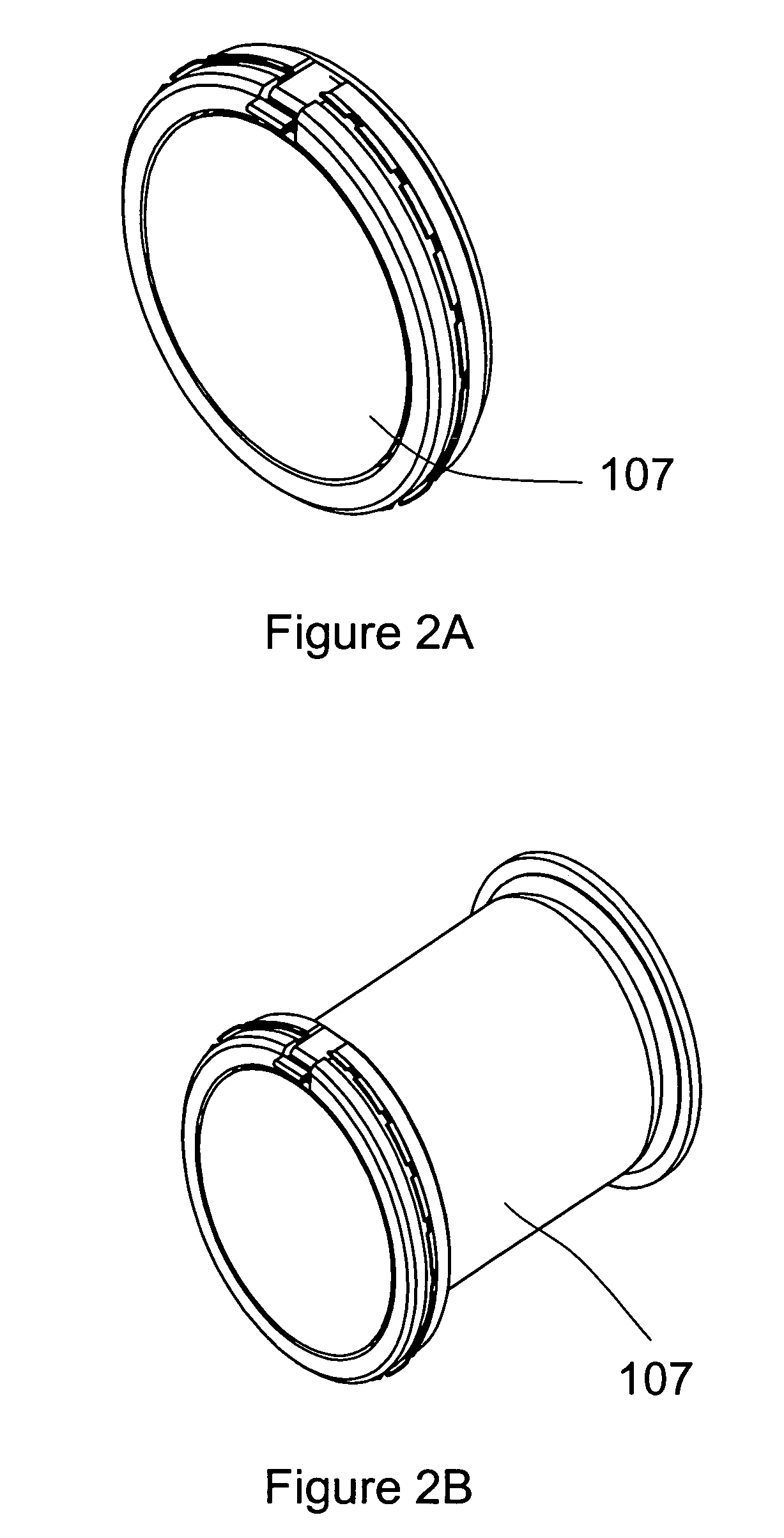
[0017]FIG. 2A shows a representative variable-force ejecting system in its inactivated state while FIG. 2B shows the ejecting system activated and ready to expel an item (submunition) 301.

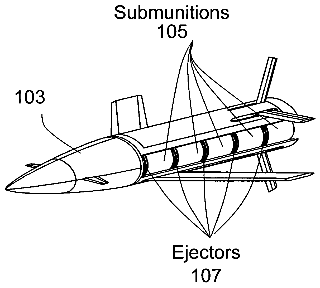
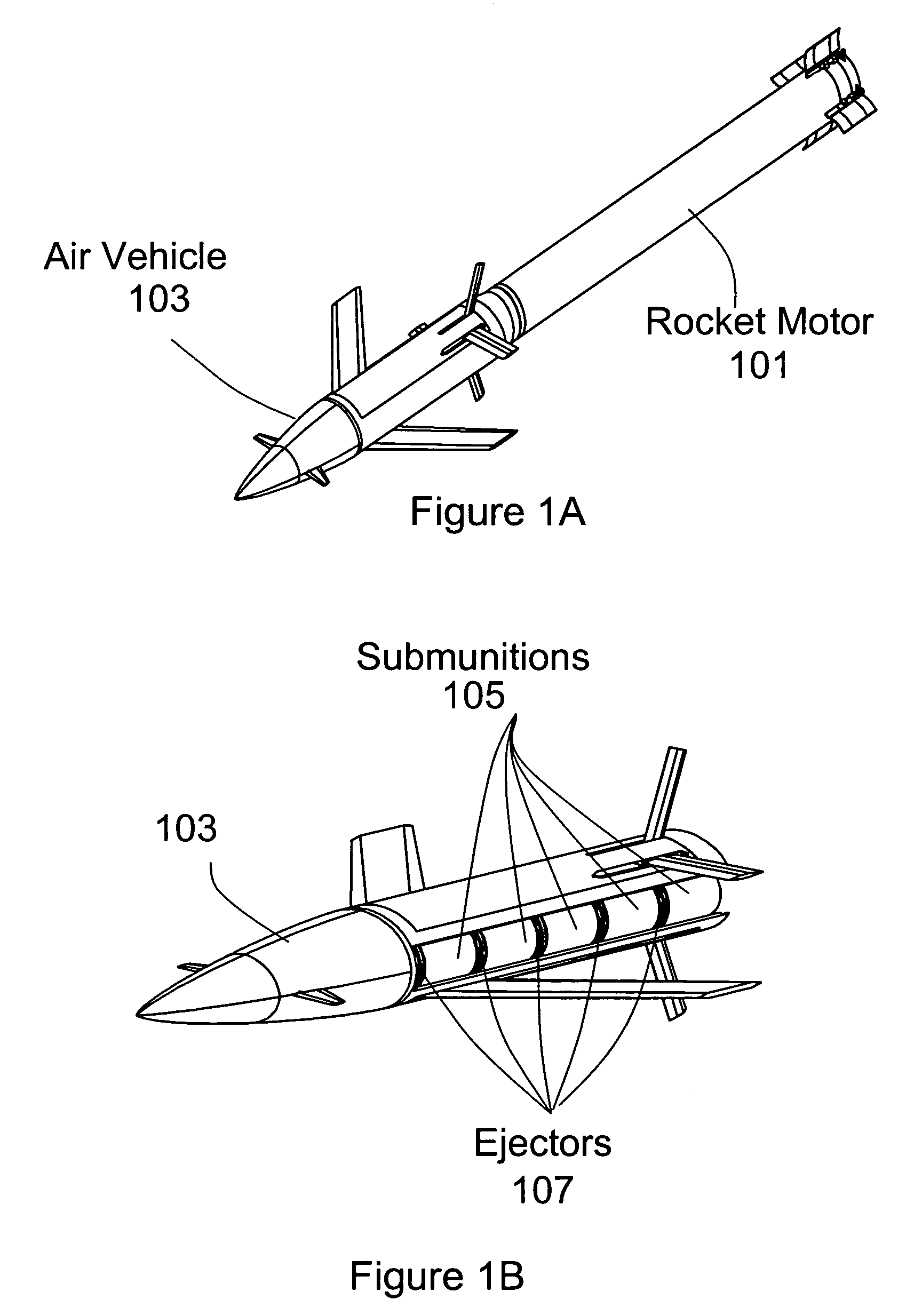
[0018]As illustrated in FIG. 1B, air ...


PUM


Abstract

The Variable-Force Payload Ejecting System, residing within an air vehicle, utilizes multiple pressure generators, one or more of which may be activated, to produce variable levels of force. A controlling computer within the air vehicle determines when and how much pressure needs to be generated to eject a given item, such as a submunition, from the vehicle. In its determination, the computer factors in the vehicle's forward velocity and height over the intended target at the time of ejection and the characteristics of the particular submunition to be ejected. An activating mechanism activates one or more pressure generators to produce the determined amount of pressure. The pressure thusly generated acts on an inflatable tube that inflates and expels the selected submunition. The result is a more precise delivery of the submunitions onto the intended targets.

Description

DEDICATORY CLAUSE[0001]The invention described herein may be manufactured, used and licensed by or for the Government for U.S. governmental purposes; provisions of 15 U.S.C. section 3710c apply.BACKGROUND OF THE INVENTION[0002]In the current state of the art in the field of ejection of an item, such as submunition or munition, from an air vehicle, there are essentially three standard techniques. The first technique involves ejecting a payload of submunitions through the nose of the vehicle by an explosive charge located behind the payload. This technique is used primarily with flechette or rod type submunitions. The second technique involves ejecting the payload through the side of the air vehicle (radial ejection). In the third technique, the submunitions are ejected from the rear of the air vehicle (axial ejection).[0003]In all of these techniques, the ejecting system is designed for a single type of submunition and utilizes a single level of force. Such an ejecting system cannot ...

Claims


Application Information

Patent Timeline
Patent Type & Authority Patents(United States)
IPC IPC(8): F42B12/58B64D1/02
CPCF42B12/62F42B3/04
Inventor BITTLE, DAVID A.JIMMERSON, GARY T.COTHRAN, JULIAN L.
Owner UNITED STATES OF AMERICA THE AS REPRESENTED BY THE SEC OF THE ARMY
Learn More