
Adjustable shade-providing building structure

a building structure and shade technology, applied in the direction of umbrellas, sunshades, walking sticks, etc., can solve the problems of not being intended, not having sufficient structure to withstand high wind, and not being able to meet building codes

Inactive Publication Date: 2008-07-01
P L PORTER
View PDF52 Cites 37 Cited by
  • Summary
  • Abstract
  • Description
  • Claims
  • Application Information

AI Technical Summary

Benefits of technology

[0009]In one aspect of the present invention, a shade structure includes a vertical column and a roof. The roof includes a cover, a framework supporting the cover, and a mount attached to a top of the column and supporting the roof for rotation to different shade positions around the column including immediately adjacent the column. The mount is located inside a perimeter defined by the cover but is spaced horizontally from a center of the cover, so that the roof can be adjusted by rotation to the different shade positions to selectively provide shade around and immediately adjacent the column throughout a sunny day.

Problems solved by technology

However, the umbrellas used in furniture are typically relatively lightweight and not intended to be left outside for extended periods of time.
Nor are they made with sufficient structure to withstand high wind, intense rain or other harsh weather conditions.
Nor are they made to meet building codes.
Also, many are complex to assemble and expensive to erect and / or install.
However, they are not free-standing, but instead require the presence of a building wall for their basic anchoring and support.
Further, though these systems are sometimes extendable, they are not adjustable around a specific center location in order to continue to provide shading in the center location as the sun moves across the sky.
Also, like umbrellas, many of these systems are not intended to withstand high wind, intense rain, or other harsh weather conditions.
In particular, the present known prior art shading systems do not provide a roof-supporting structure sufficient to withstand high wind (such as 90 mph wind loads) where the structure is also adjustable to maintain shading in a particular area as the sun moves across the sky.
Further, the known shading systems that are more durable tend to lack style and elegance.
Further, they include multiple components, making them expensive to purchase, cumbersome to assemble, expensive to erect and / or build, and difficult and expensive to repair.

Method used


Image

  • Adjustable shade-providing building structure
  • Adjustable shade-providing building structure
  • Adjustable shade-providing building structure

Examples


Embodiment Construction

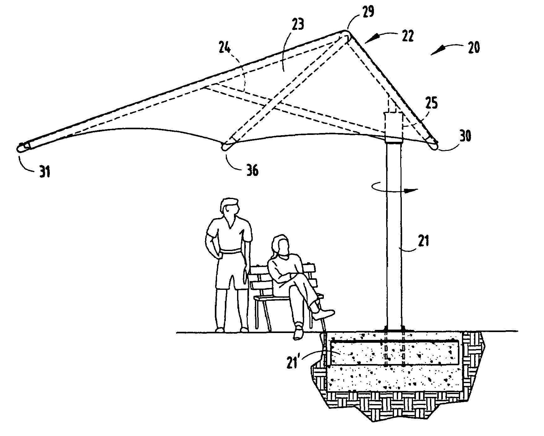
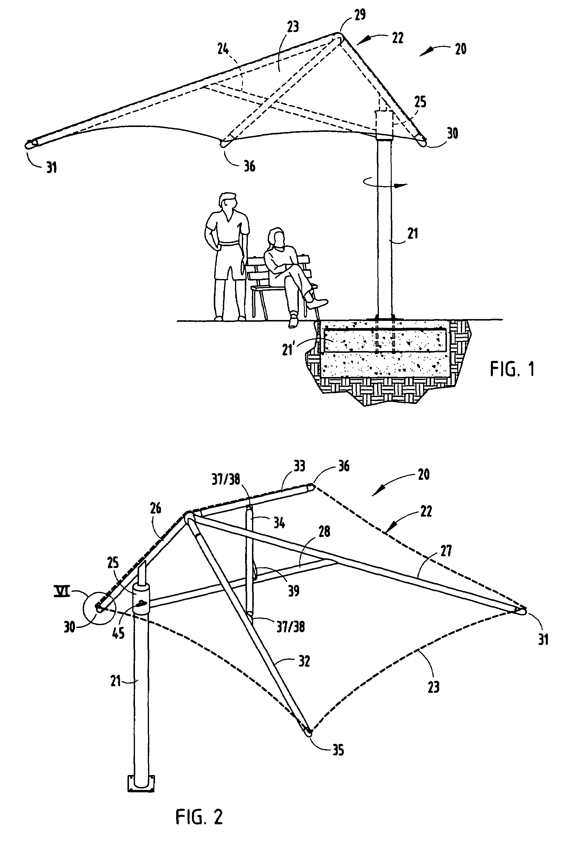
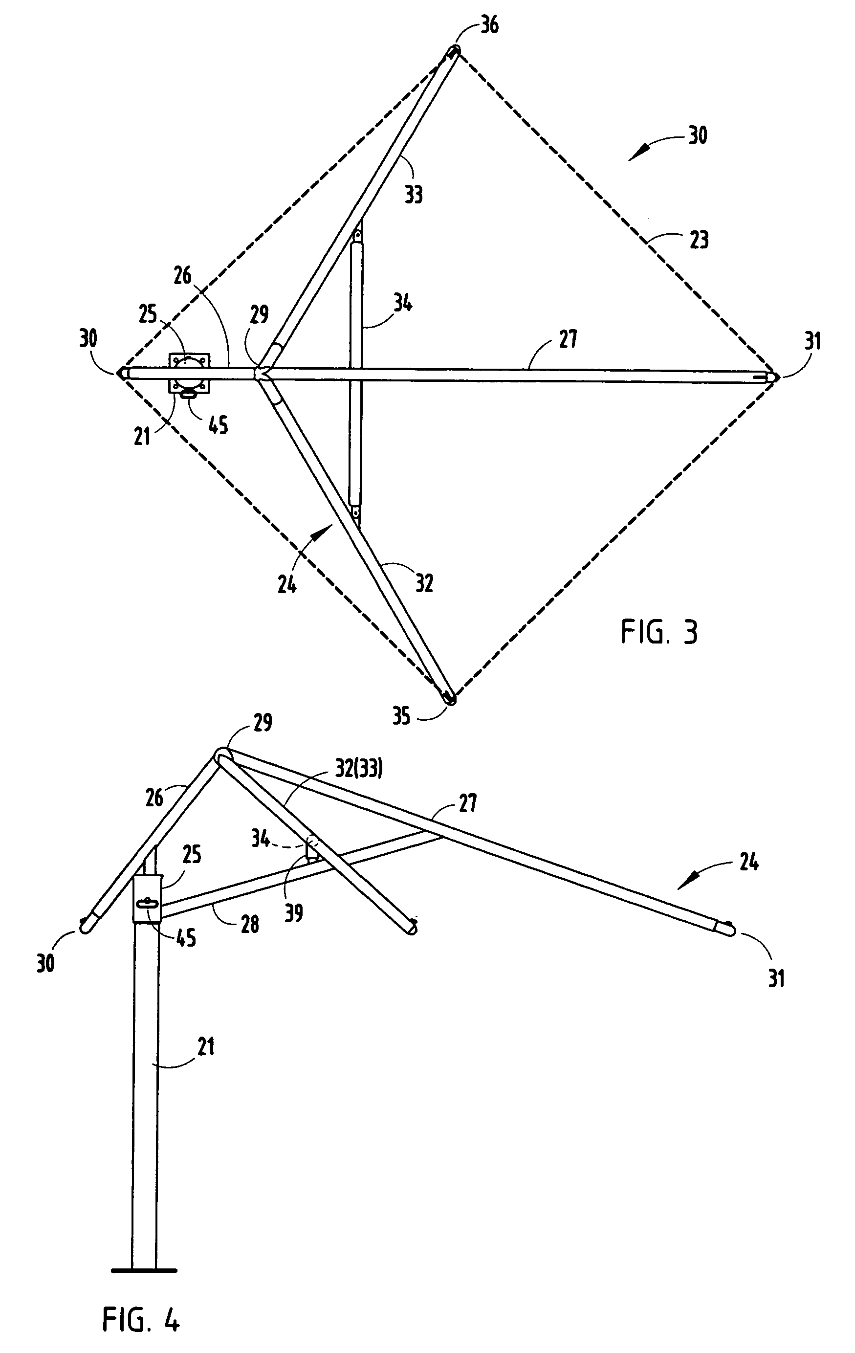
[0031]A shade structure 20 (FIG. 1-2) includes a vertical column 21 and a roof 22 having a cover 23, a framework 24 supporting the cover 23, and a mount 25 attached to a top of the column 21 and rotatably supporting the roof 22 on the column 21. The framework 24 includes a triangularly-shaped main beam arrangement (FIG. 4) comprising a plurality of beams 26-28 secured together to form a triangular that lies in a vertical plane and that defines a peak 29 and opposing first corners 30 and 31, with the mount 25 being located between the peak 29 and one of the opposing corners 30 and 31. The framework 24 further includes a pair of transverse beams 32 and 33, stabilized by a transverse bracing beam 34. The inner ends of the beams 32 and 33 are secured to the triangular main beam arrangement at the peak and include ends that define opposing outer (lateral) second corners 35 and 36 of the shading arrangement. The bracing beam 34 (FIGS. 9-10) includes longitudinally-extending end flanges 37...


PUM


Abstract

A shade structure includes a vertical column and a roof having a cover, a framework supporting the cover, and a mount attached for rotational adjustment to a top of the column and supporting the roof on the column. The framework includes a triangularly-shaped main beam arrangement comprising a plurality of beams secured together to form a triangle that lies in a vertical plane and that defines a peak and opposing first corners, with the mount being located between the peak and one of the opposing corners. The framework further includes a pair of transverse beams and a bracing beam secured to the triangular main beam arrangement that define opposing second corners. By this arrangement, an adjustable shade structure is provided that is able to withstand over 40 mph wind loads.

Description

BACKGROUND[0001]The present invention relates to an adjustable shade-providing building structure, and more particularly relates to a structure configured to provide adjustable shading in an outdoor open environment, but that is also configured to meet many building codes and to provide greater durability and permanency than umbrella furniture systems and traditional shading systems that will not withstand wind loads.[0002]Many establishments require (or desire) shading structures to facilitate and promote outdoor activities. For example, furniture with umbrellas are often used in outdoor restaurants, picnic areas and beaches to provide shade from the sun while allowing users to enjoy the sun and outdoor areas. However, the umbrellas used in furniture are typically relatively lightweight and not intended to be left outside for extended periods of time. Nor are they made with sufficient structure to withstand high wind, intense rain or other harsh weather conditions. Nor are they mad...

Claims


Application Information

Patent Timeline
Patent Type & Authority Patents(United States)
IPC IPC(8): E04H15/34
CPCA45B23/00E04H15/28E04F10/02A45B2023/0012A45B2023/0025
Inventor PORTER, ANDREW H.PORTER, WILLIAM H.
Owner P L PORTER
Learn More