Eureka AIR delivers breakthrough ideas for toughest innovation challenges, trusted by R&D personnel around the world.

Gain control method and apparatus

a gain control and gain control technology, applied in the field of wireless communication, can solve the problems of affecting and the output of the adc may be saturated, so as to achieve the effect of improving the performance of the communication system

Inactive Publication Date: 2008-06-24
INTERDIGITAL TECH CORP
View PDF20 Cites 2 Cited by
  • Summary
  • Abstract
  • Description
  • Claims
  • Application Information

AI Technical Summary

Benefits of technology

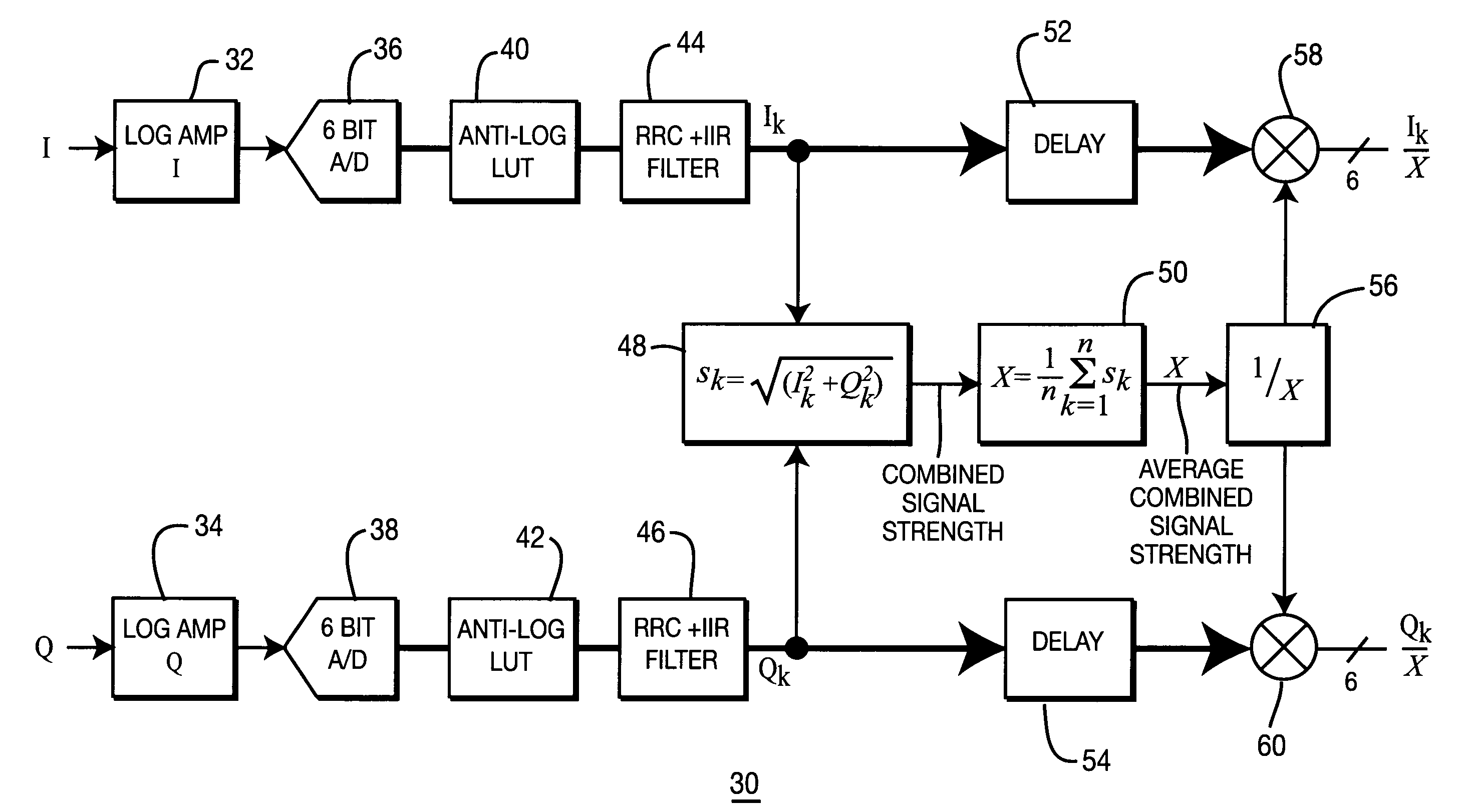
[0005]The present invention overcomes the problems confronting the techniques presently in use by compressing an input analog signal at baseband and employing a logarithmic technique, converting the compressed signal into digital form and expanding the digital signal to its original linear scale using an antilog technique. Word size of the expanded digital signal may be reduced by a normalization technique.

Problems solved by technology

However, this results in a more expensive ADC, as well as the rest of the receiver components.
Given the number of output bits, if the power of the input signal is too large, the output of the ADC may be saturated.
On the other hand, if the power of the input signal is too small, the input signal may be severely quantized.
In both of these cases, the information to be recovered at the receiver may be lost.
AGC requires a specific radio architecture with gain control, both of which add cost and power consumption.
The higher the gain before the down-converter (demodulator) the better (lower) the NF, but the IP3 is also lowered (which is not good).
In practice, some of the above requirements are difficult to achieve.
Certain trade-offs have to be made, resulting in a loss of a certain amount of system level performance.

Method used


Image

  • Gain control method and apparatus
  • Gain control method and apparatus
  • Gain control method and apparatus

Examples


Embodiment Construction

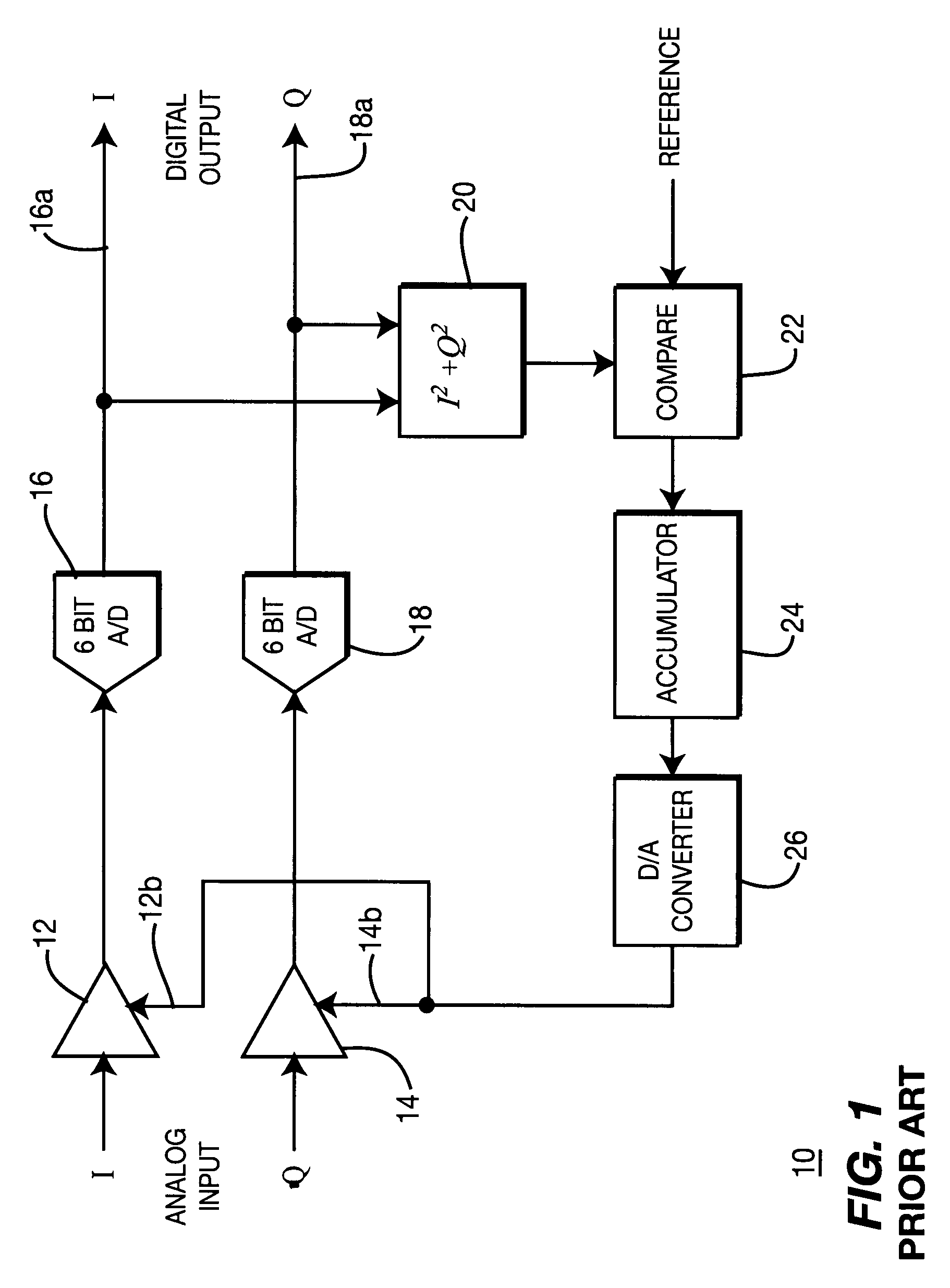
[0010]FIG. 1 shows a prior art closed-loop automatic gain control (AGC) circuit 10 in which analog inputs of in-phase (I) and quadrature (Q) signals are respectively applied to amplifiers 12 and 14. The outputs thereof undergo analog to digital conversion through A / D converters 16, 18 which are shown in FIG. 1 as, (e.g., 6 bit), A / D converters, providing I and Q outputs at 16a and 18a, respectively.

[0011]The outputs of A / D converters 16 and 18 are applied to circuit 20 to obtain a sum of I2+Q2 which is then compared to a reference level in comparison circuit 22. The output of comparison circuit 22 is applied to a digital-to-analog converter (DAC) 26 through an accumulator 24 and respectively applied to the gain control inputs 12b, 14b of the gain control amplifiers 12 and 14.

[0012]The all digital gain control (ADGC) device 30 of the present invention avoids some of the requirements associated with the nature of the closed-loop AGC circuitry described above, and meets the remaining r...


PUM


Abstract

An analog / digital gain control device avoid some of the requirements associated with the nature of a closed-loop AGC circuits and which meets the remaining requirements without much difficulty uses an analog to digital conversion method that increases the number of effective ADC bits by compressing the baseband input analog signal using a logarithmic circuit. After the compressed analog signal is converted into a digital signal, a digital anti-log process or look-up table (LUT) is used to expand the digital signal back to the original linear scale. The word size of the output of the anti-log process is larger than the input word size due to the nature of the anti-log function. To reduce the word size of the digital signal an open loop normalization technique can be applied.

Description

CROSS REFERENCE TO RELATED APPLICATIONS[0001]This application is a continuation of U.S. patent application Ser. No. 10 / 330,749 filed on Dec. 27, 2002, now U.S. Pat. No. 7,233,624 which claims the benefit of U.S. Provisional Patent Application No. 60 / 388,122 filed on Jun. 11, 2002, which are incorporated by reference as if fully set forth.FIELD OF INVENTION[0002]The present invention relates to the field of wireless communications. More specifically, the present invention relates to an all digital gain control architecture.BACKGROUND[0003]In most wireless communication systems, the baseband signal at a receiver is converted from analog format into digital format so that the useful information can be recovered via a sequence of digital processes. The common device that achieves this conversion is an analog-to-digital converter (ADC). One of the most important specifications of an ADC is the number of output bits. In general, the more output bits the ADC has, the larger the dynamic ran...

Claims


Application Information

Patent Timeline
Patent Type & Authority Patents(United States)
IPC IPC(8): H04B14/04H03M1/18H03G3/00H03G3/20H03G3/30H03G7/06H03M1/12H04B17/40
CPCH03G3/001H03M1/1235H03G7/06H04B17/40
Inventor KAZAKEVICH, LEONIDYANG, RUI
Owner INTERDIGITAL TECH CORP
Why Eureka
Eureka Blog
Learn More