Optical disk recording/reproducing apparatus
a technology of optical disk and recording device, which is applied in the direction of data recording, instruments, disposition/mounting of heads, etc., can solve the problems of deterioration of tracking error signal, further deterioration of signal (dpp•te signal), lowering of tracking servo accuracy, etc., and achieves the effect of suppressing the deterioration in quality of tracking error signal and improving the accuracy of tracking servo
- Summary
- Abstract
- Description
- Claims
- Application Information
AI Technical Summary
Benefits of technology
Problems solved by technology
Method used
Image


Examples
first embodiment
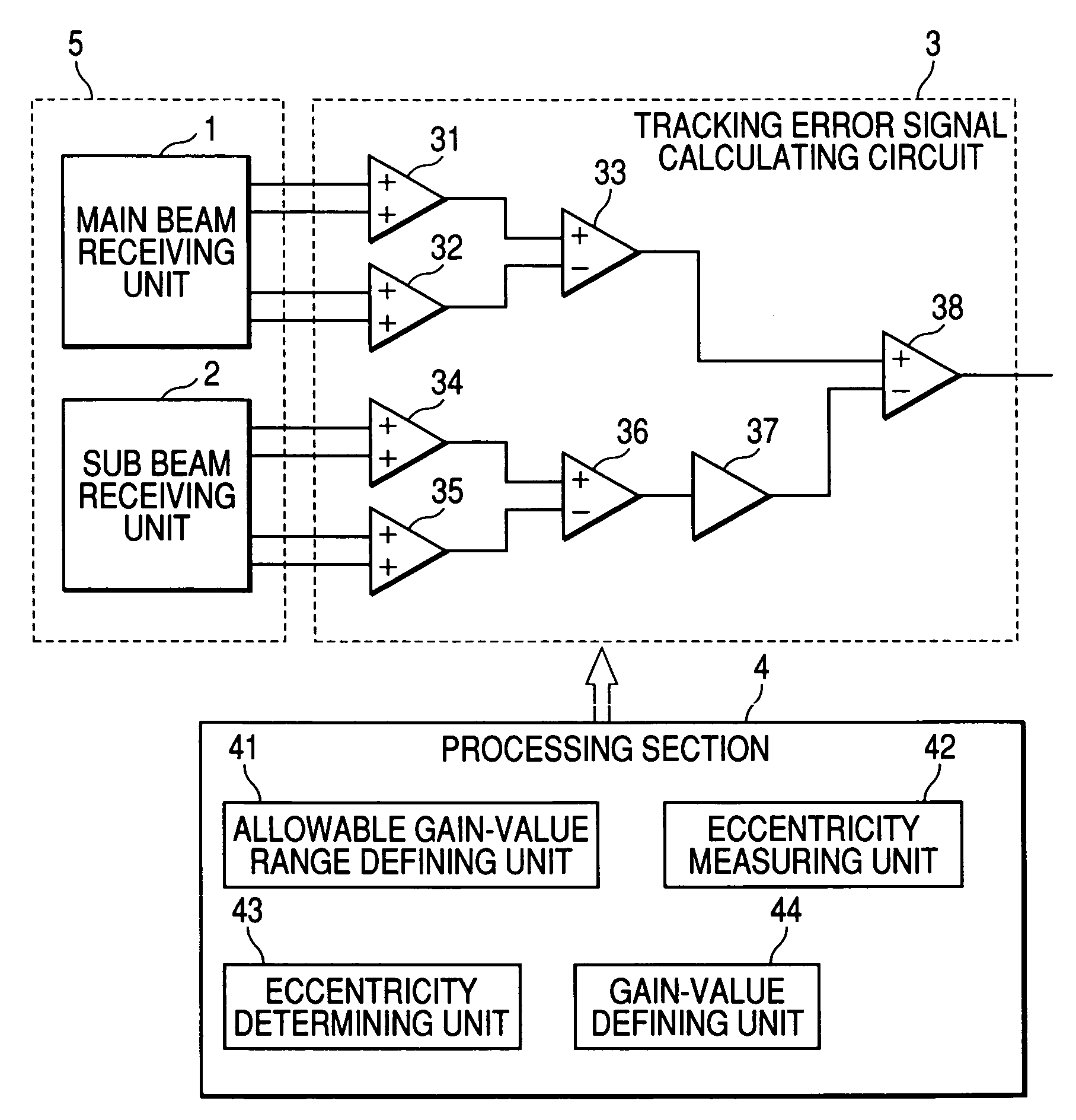
[0041]Now, embodiments of the present invention will be described with reference to the accompanying drawings. FIG. 1 is a block diagram showing configurations of a tracking error signal calculating circuit and a processing section in an optical disk recording / reproducing apparatus according to the present invention.
[0042]The optical disk recording / reproducing apparatus includes an optical pickup 5, a tracking error signal calculating circuit 3, and a processing section 4. The optical pickup 5 emits a laser beam containing main and sub beams on an optical disk and includes a main beam receiving unit 1 for receiving a main beam reflected from a target track of the optical disk and a sub beam receiving unit 2 for receiving a sub beam reflected from a position deviated from the target track.
[0043]The main beam receiving unit 1 includes four partitioned main photo-detectors 21 (see FIG. 2) for receiving the reflected main beam reflected from the target track of the optical disk, and the...
second embodiment
[0056]FIG. 4 is a block diagram showing configurations of a tracking error signal calculating circuit and a processing section in an optical disk recording / reproducing apparatus according to the present invention. In FIG. 4, the same components as those of FIG. 1 are indicated by the same reference numerals, and the detailed description thereof is omitted.
[0057]In FIG. 4, the processing section 6 includes maximum gain-value defining unit 61 for measuring the gain value k corresponding to a level ratio between the main push-pull signal (MPP signal) and the sub push-pull signal (SPP signal) to define an maximum value of the gain value k, eccentricity measuring unit 62 for measuring an eccentricity of the optical disk based on the sub push-pull signal (SPP signal), eccentricity determining unit 63 for determining whether or not the measured eccentricity is greater than or equal to a predetermined value, maximum gain-value re-measuring unit 64 for defining one of preceding and following...
third embodiment
[0064]FIG. 6 is a block diagram showing configurations of a tracking error signal calculating circuit and a processing section in an optical disk recording / reproducing apparatus according to the present invention. In FIG. 6, the same components as those of FIG. 1 are indicated by the same reference numerals, and the detailed description thereof is omitted.
[0065]In FIG. 6, the processing section 7 includes allowable gain-value range defining unit 71 for measuring the gain value corresponding to a level ratio between the main push-pull signal (MPP signal) and the sub push-pull signal (SPP signal) to define an allowable range of the gain value, sub push-pull signal amplitude measuring unit 72 for measuring an amplitude of the sub push-pull signal (SPP signal), amplitude-variation determining unit 73 for determining whether or not a variation in the measured amplitude is greater than or equal to a predetermined value, and gain-value defining unit 74 for selecting a minimum value of the ...
PUM
| Property | Measurement | Unit |
|---|---|---|
| distance | aaaaa | aaaaa |
| phase | aaaaa | aaaaa |
| recording density | aaaaa | aaaaa |
Abstract
Description
Claims
Application Information
 - R&D
- Intellectual Property
- Life Sciences
- Materials
- Tech Scout
- Unparalleled Data Quality
- Higher Quality Content
- 60% Fewer Hallucinations
Browse by: Latest US Patents, China's latest patents, Technical Efficacy Thesaurus, Application Domain, Technology Topic, Popular Technical Reports.
© 2025 PatSnap. All rights reserved.Legal|Privacy policy|Modern Slavery Act Transparency Statement|Sitemap|About US| Contact US: help@patsnap.com