
Linear guide bearing apparatus

a bearing and guide technology, applied in the direction of bearings, bearings, shafts and bearings, etc., can solve the problems of reducing the number of parts, affecting the quality of the bearing, so as to prevent the deterioration or vaporization of any lubricant, the effect of preventing fine dus

Active Publication Date: 2008-06-17
NSK LTD
View PDF12 Cites 7 Cited by
  • Summary
  • Abstract
  • Description
  • Claims
  • Application Information

AI Technical Summary

Benefits of technology

The present invention provides a linear guide bearing apparatus that prevents fine dust and other debris from entering the slider through between lubricant feeding members when multiple lubricant feeding members are used. This prevents deterioration of the lubricant and the components of the apparatus. The apparatus includes a guide rail, a slider, and a lubricant feeding member. A pressing member is also included to exert pressure on the lubricant feeding member and ensure efficient lubricant feeding. The apparatus is easy to assemble and requires a small number of parts.

Problems solved by technology

Moreover, as the lubricant feeding member 15 is open to its outside and has an exposed outer periphery, there have been occurred undesirably problems that the lubricant on its outer periphery may easily be deteriorated or vaporize, and that the lubricant may not be fed to the rolling body rolling grooves 3 efficiently, and the lubricant may be lost or deteriorated in an accelerated way under the influence of any coolant, organic solvent, etc used when the apparatus is in operation.
Further, for each one of the lubricant feeding member 15, one pressing member 18 and one fixing ring 16 are required, which lead to increase number of parts, and make complicate to assemble the apparatus.
Further, according to the known linear guide bearing apparatus as described, the side seals 11 sealing the ends of the slider 2 are rubber seals and present difficulty in the complete removal of finely divided foreign matter.
Moreover, the heat generated by sliding friction between the side seals 11 and the guide rail 1 and the sliding wear of their lips lower their sealing performance and disable them to exhibit any satisfactory dust-proofing result.

Method used


Image

  • Linear guide bearing apparatus
  • Linear guide bearing apparatus
  • Linear guide bearing apparatus

Examples


first embodiment

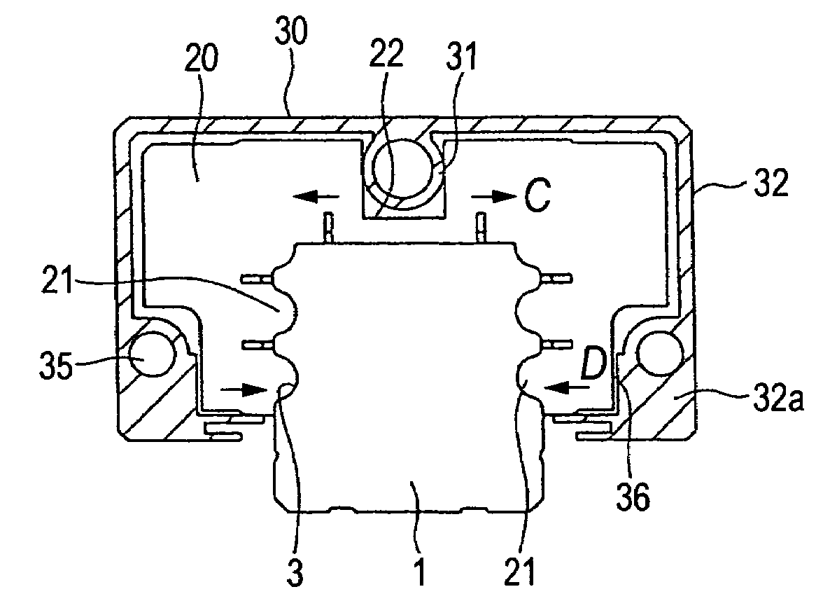
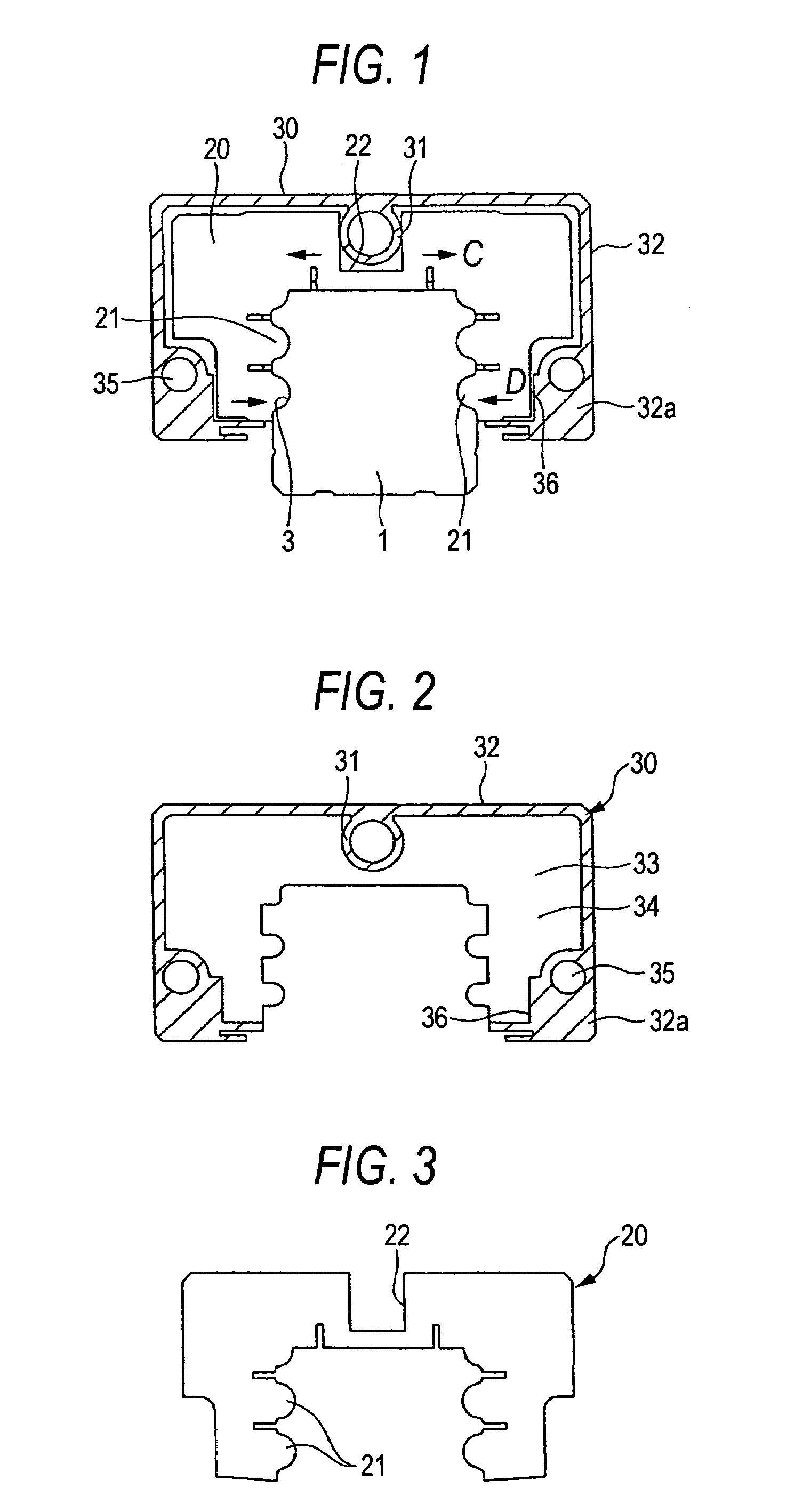
[0062]the present invention will now be described with reference to drawings. FIG. 1 is a sectional view for explaining a linear guide bearing apparatus according to an embodiment of the present invention. FIG. 2 is a sectional view showing a casing. FIG. 3 is a diagram showing a lubricant feeding member. FIG. 4 is a sectional view showing the shape of a portion in which the sliding contact portion of the lubricant feeding member is pressed against the rolling body rolling grooves of the guide rail. FIG. 5 is a sectional view showing a modified embodiment of pressing member. FIGS. 6 to 9 are each a sectional view showing modified embodiments of the portion in which the sliding contact portion of the lubricant feeding member is pressed against the rolling body rolling grooves of the guide rail. Those parts which the device embodying the present invention shares with the known linear guide bearing apparatus as described with reference to FIG. 12 are denoted by the same symbols through...

second embodiment

[0074]A second embodiment according to the second aspect of the present invention will now be described with reference to drawings. FIG. 10 is a perspective view, partly in section, for explaining the essential part of a linear guide bearing apparatus according to the embodiment of the present invention and FIG. 11 is a diagram showing one form of a sealing member.

[0075]In the linear guide bearing apparatus according to the embodiment of the present invention, a sealing member 115 making sliding contact with the rolling body rolling grooves 103 of a guide rail 101 and sealing each axial end of a slider 102 is composed of a plurality of sheets arranged axially of the slider 102 and housed in a casing 20 on the outside of an end cap 105, as shown in FIG. 10.

[0076]The sealing member 115 is formed from a porous felt material composed of e.g. synthetic resin fibers and containing a lubricant, such as lubricant oil or grease. The sealing member 115 has a substantially U-shaped form as wel...


PUM


Abstract

In a linear guide bearing apparatus in which a lubricant feeding member 20 attached to an axial end of a slider 2 and making sliding contact with the rolling body rolling grooves 3 of a guide rail 1 to feed a lubricant thereto is of a porous material containing the lubricant and is pressed outwardly along the width of the slider 2 by a pressing member 31 fitted in the lubricant feeding member 20 at an upper portion thereof to have its sliding contact portions 21 pressed against the rolling body rolling grooves 3 of the guide rail 1, the lubricant feeding member 20 is housed in the casing 30 formed integrally with the pressing member 31.

Description

[0001]The present invention claims foreign priority to Japanese patent application no. P.2004-229604, filed on Aug. 5, 2004 and no. P.2004-242489, filed on Aug. 23, 2004, the contents of which are incorporated herein by references.BACKGROUND OF THE INVENTION[0002]1. Field of the Invention[0003]The present invention relates to a linear guide bearing apparatus used in any of various kinds of machines and apparatus, such as a machine tool, robot or measuring instrument.[0004]2. Description of the Background Art[0005]A known linear guide bearing apparatus of this type is shown in, for example, FIG. 12. This linear guide bearing apparatus has an axially extending guide rail 1 and a slider 2 mounted about the guide rail 1 axially movably relative to the guide rail 1.[0006]The guide rail 1 has an axially extending rolling body rolling groove 3 formed in each of two sidewalls thereof. The slider 2 has a rolling body rolling groove 7 formed in the inner surface of each of two legs 4 of a mai...

Claims


Application Information

Patent Timeline
Patent Type & Authority Patents(United States)
IPC IPC(8): F16C29/06
CPCF16C29/0609F16C29/0642F16C33/6611F16C33/6648F16C29/086
Inventor UBUKATA, HIROMASAABE, YASUSHI
Owner NSK LTD
Learn More