Air-operated end prep machine

a prep machine and air-operated technology, applied in the field of refinishing tools for workpieces, can solve the problems of not always achieving a true phonographic finish to workpieces

Inactive Publication Date: 2008-06-10
HYDRATIGHT OPERATIONS INC
View PDF11 Cites 23 Cited by
  • Summary
  • Abstract
  • Description
  • Claims
  • Application Information

AI Technical Summary

Problems solved by technology

While the prior art end prep lathes are useful for refurbishing work pieces, reliance on tripper mechanisms to advance the cutting tool does not always lead to a true phonographic finish to the work piece.

Method used


Image

  • Air-operated end prep machine
  • Air-operated end prep machine
  • Air-operated end prep machine

Examples


Embodiment Construction

[0013]Certain terminology will be used in the following description for convenience in reference only and will not be limiting. The words “upwardly”, “downwardly”, “rightwardly” and “leftwardly” will refer to directions in the drawings to which reference is made. The words “inwardly” and “outwardly” will refer to directions toward and away from, respectively, the geometric center of the device and associated parts thereof. Said terminology will include the words above, specifically mentioned, derivatives thereof and words of similar import.

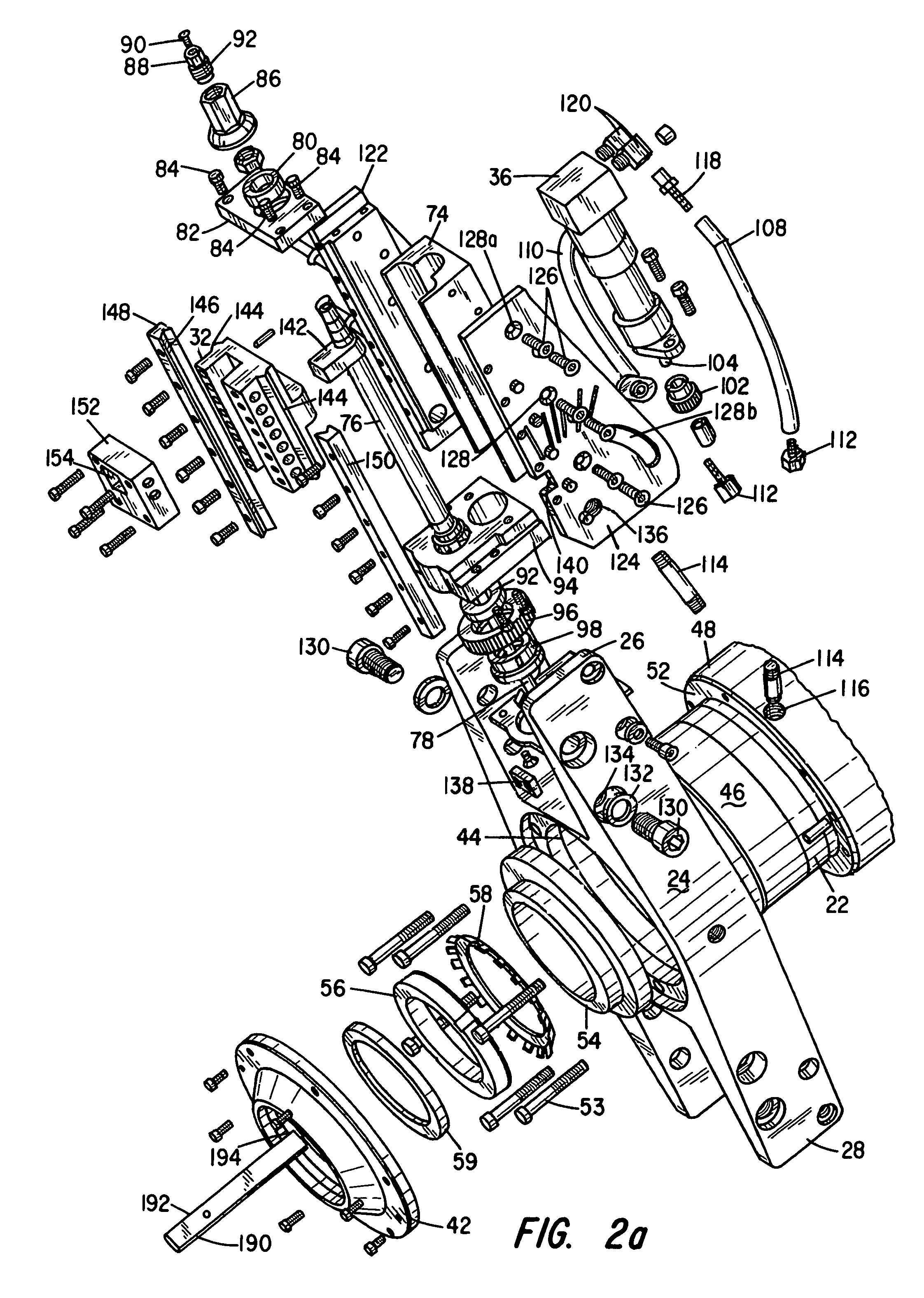
[0014]FIG. 1 is a perspective view of the preferred embodiment of the end prep tool of the present invention. The end prep tool is generally designated by the numeral 10. The mounting mandrel clamping assembly 12 includes a base member 14 and the stem member 16. The stem member 16 supports the rotatable assembly 18 and the stationary housing 20 thereon. The rotatable assembly 18 comprises a rotatable housing 22 supporting a head assembly 24. The h...


PUM

PropertyMeasurementUnit
diameteraaaaaaaaaa
poweraaaaaaaaaa
displacementaaaaaaaaaa

Abstract

An end prep tool with a pneumatically driven tool slide assembly comprises a mandrel mountable to the internal diameter of a tubular work piece. Mounted on the mandrel are a rotational head assembly and a rotatable housing that are longitudinally displaceable along the mandrel. The rotational head assembly carries either one or two tool feed assemblies thereon for orbital movement around the work piece. The tool slide assemblies are driven by a pneumatic motor to provide a true phonographic finish with no tripper marks.

Description

BACKGROUND OF THE INVENTION[0001]I. Field of the Invention[0002]This invention relates generally to tools for refinishing a work piece and more particularly, to an internally mounted end prep tool that can be rapidly set up and used in the field to accurately machine flat or beveled surfaces on pipe flanges, valves, fittings and pipe ends within close tolerance ranges.[0003]II. Discussion of the Prior Art[0004]Portable end prep tools are generally known in the art. Industrial tubing is found in refineries, pipelines, steam plants or the like. End prep tools are used to prepare industrial tubing for welding by cutting, machining and / or beveling the end of the tube. Prior art end prep machines mount or clamp to the inside surface of the work piece with an adjustable mandrel. Mounted on the mandrel is an annular housing supporting a gear ring carrying either one or two tool feed assemblies thereon for orbital and radial movement of the cutting tool relative to the work piece. In the U....

Claims


Application Information

Patent Timeline
Patent Type & Authority Patents(United States)
IPC IPC(8): B23B3/22B23B5/16
CPCB23B5/162B23B2270/22Y10T82/22Y10T82/2522Y10T82/2539
Inventor PLACE, BRENTRICCI, DONATO L.
Owner HYDRATIGHT OPERATIONS INC
Why Eureka
Try Eureka