
Systems, methods and apparatus of a composite X-Ray target

a composite and target technology, applied in the field of x-ray targets, can solve the problems of limiting the rate of x-ray images, large x-ray targets in computed tomography systems, and x-ray targets in x-ray imaging systems also have a limiting mechanical factor in the strength of graphite materials,

Active Publication Date: 2008-06-03
GENERAL ELECTRIC CO
View PDF10 Cites 31 Cited by
  • Summary
  • Abstract
  • Description
  • Claims
  • Application Information

AI Technical Summary

Benefits of technology

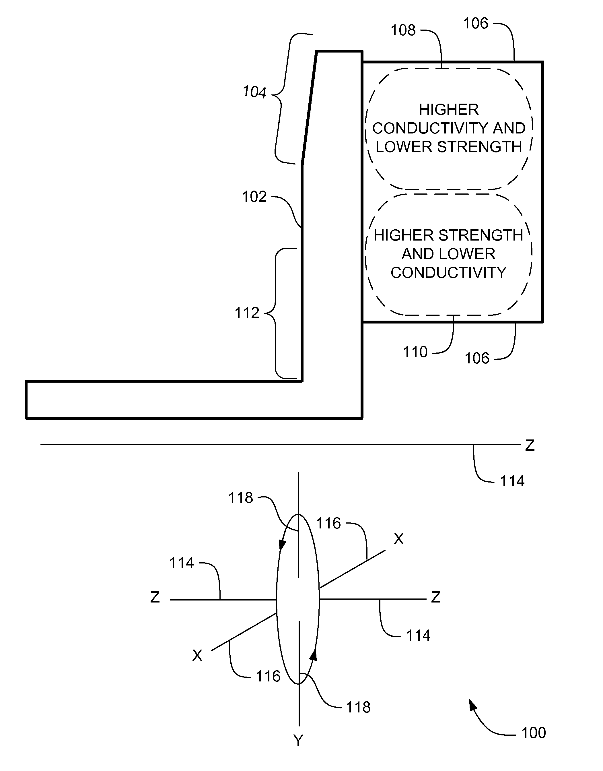
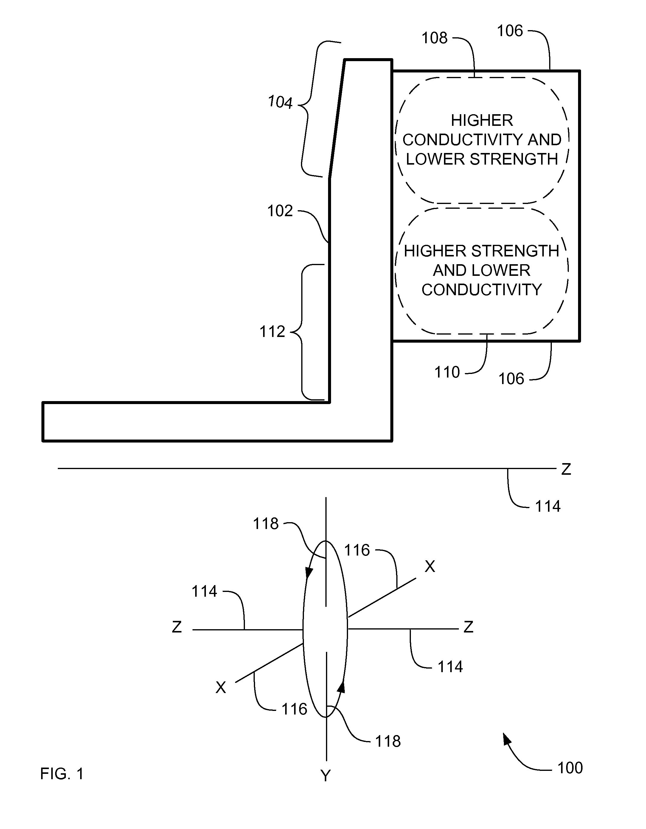
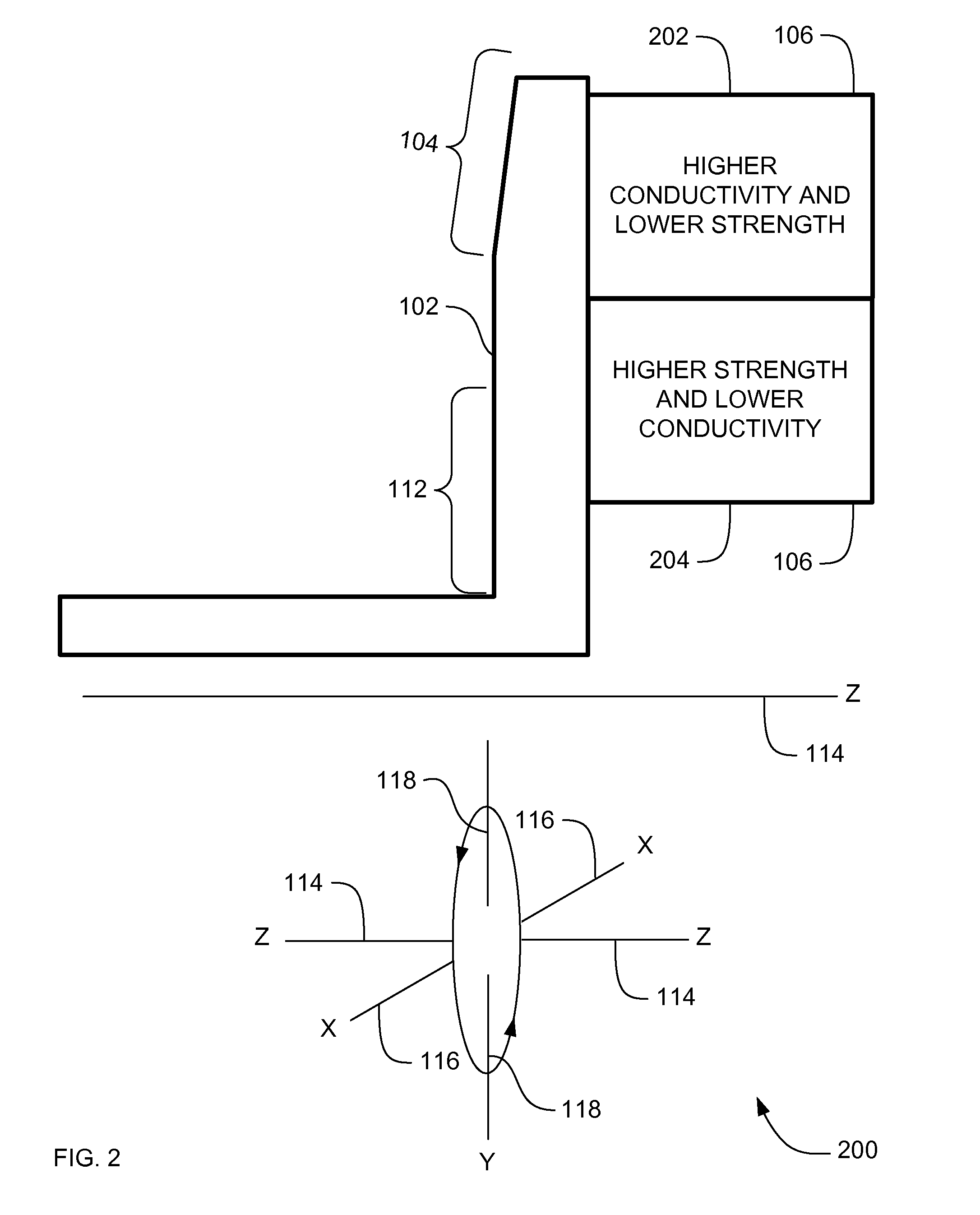
[0012]The variation in strength and thermal conductive properties throughout the X-Ray target provides an X-Ray target that has increased mechanical strength without decreased thermal conductivity.

Problems solved by technology

Large X-Ray targets in computed tomography systems have a limiting mechanical factor in the strength of the graphite material.
X-Ray targets in X-Ray imaging systems also have a limiting mechanical factor in the thermal conductivity of the graphite material.
The rate of emitted X-Ray energy limits the rate of X-Ray images that can be made by the X-Ray imaging systems, and limits the usefulness of the conventional X-Ray imaging systems.
However, in order to create a graphite material with higher strength, the thermal conductivity properties of the material are adversely affected in X-Ray targets because higher strength graphite typically has lower thermal conductivity.

Method used


Image

  • Systems, methods and apparatus of a composite X-Ray target
  • Systems, methods and apparatus of a composite X-Ray target
  • Systems, methods and apparatus of a composite X-Ray target

Examples


Embodiment Construction

[0023]In the following detailed description, reference is made to the accompanying drawings that form a part hereof, and in which is shown by way of illustration specific embodiments which may be practiced. These embodiments are described in sufficient detail to enable those skilled in the art to practice the embodiments, and it is to be understood that other embodiments may be utilized and that logical, mechanical, electrical and other changes may be made without departing from the scope of the embodiments. The following detailed description is, therefore, not to be taken in a limiting sense.

[0024]The detailed description is divided into four sections. In the first section, a system level overview is described. In the second section, apparatus of embodiments are described. In the third section, embodiments of methods are described. Finally, in the fourth section, a conclusion of the detailed description is provided.

System Level Overview

[0025]FIG. 1 is a cross section block diagram ...


PUM

PropertyMeasurementUnit
thermal conductivityaaaaaaaaaa
temperaturesaaaaaaaaaa

Abstract

Systems, methods and apparatus are provided through which in some embodiments an X-Ray energy target includes composite material that varies spatially in thermal properties, and in some embodiments, the composite material varies spatially in strength properties. In some embodiments, the spatial variance is a continuum and in other embodiments, the spatial variance is a plurality of distinct portions.

Description

FIELD OF THE INVENTION[0001]This invention relates generally to electromagnetic energy targets, and more particularly to X-Ray targets.BACKGROUND OF THE INVENTION[0002]X-Ray imaging systems have an X-Ray target. In conventional X-Ray targets, graphite is brazed to a high temperature capable material. Thermal storage is provided by the graphite.[0003]Large X-Ray targets in computed tomography systems have a limiting mechanical factor in the strength of the graphite material. In computed tomography systems, a gantry rotates at approximately three revolutions per second around a patient and an anode having the X-Ray target rotates at 100 to 200 revolutions per second. The rotation creates large centripetal forces on the X-Ray target that increases exponentially as the size of the X-Ray target increases.[0004]X-Ray targets in X-Ray imaging systems also have a limiting mechanical factor in the thermal conductivity of the graphite material. The X-Ray target must be able to conduct heat at...

Claims


Application Information

Patent Timeline
Patent Type & Authority Patents(United States)
IPC IPC(8): H01J35/08H01J35/10
CPCH01J35/101H01J35/105H01J2235/083H01J2235/1046H01J2235/1204H01J2235/1291H01J35/1017
Inventor HEBERT, MICHAEL SCOTTSTEINLAGE, GREGORY ALAN
Owner GENERAL ELECTRIC CO
Learn More