
UHF RFID tag and method of manufacturing the same

a radio frequency identification and ultra high frequency technology, applied in the direction of instruments, resonant antennas, burglar alarm mechanical actuation, etc., can solve the problems of short or open circuit, rfid tag damage, complicated manufacturing process, etc., and achieve the effect of reducing size, rapid and easy operation

Inactive Publication Date: 2008-06-03
HANWHA TECHWIN CO LTD
View PDF9 Cites 5 Cited by
  • Summary
  • Abstract
  • Description
  • Claims
  • Application Information

AI Technical Summary

Benefits of technology

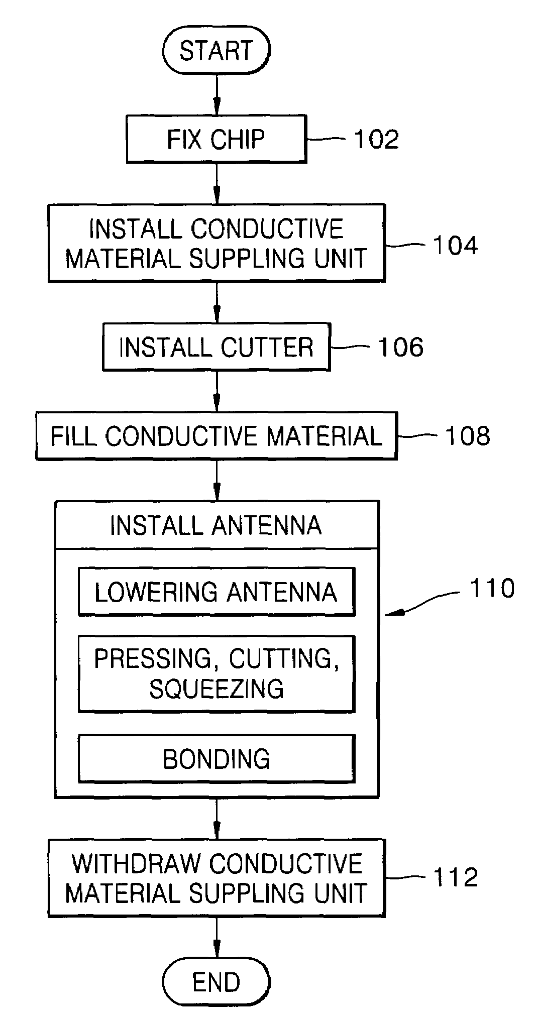
The present invention provides an ultra high frequency (UHF) radio frequency identification (RFID) tag and a method of manufacturing it. The UHF RFID tag has a reduced size because it employs a plurality of short UHF antennas instead of a loop-type antenna. The chip and UHF antenna are easily connected using a conductive paste. The UHF antenna is installed on the chip by lowering it to a cutter and then continuously lowering it until it reaches the substrate. The method includes fixing the chip to the substrate, installing a cutter, lowering the UHF antenna to the cutter, cutting the antenna, and bonding it to the substrate. The UHF RFID tag has a smaller size and is easier to manufacture than other RFID tags.

Problems solved by technology

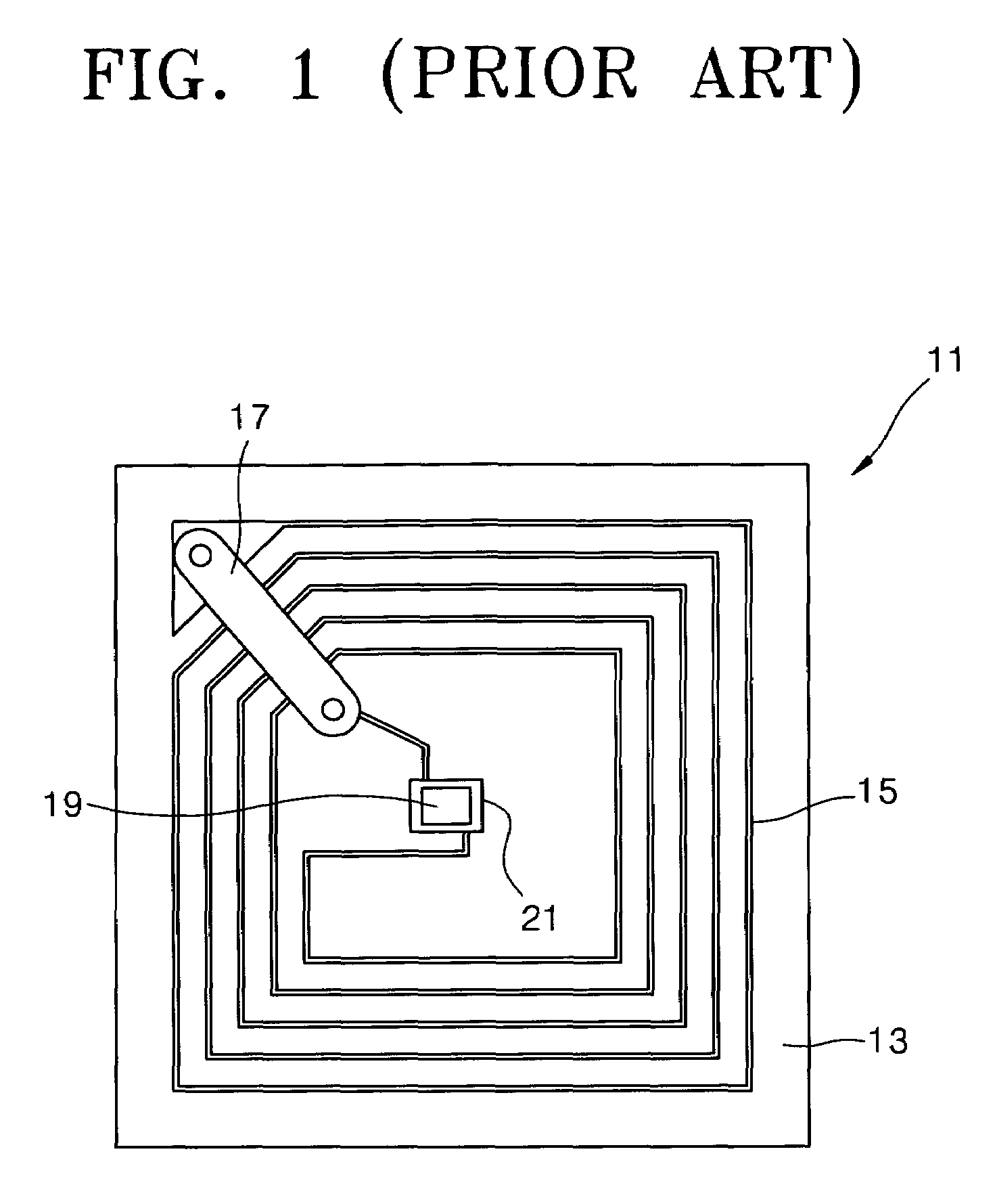
Moreover, the illustrated antenna 15 may easily become damaged or scratched resulting in a short or open circuit.
In this case, the RFID tag may become damaged in the process of preparing the RFID tag (e.g., peeling off a backing from an adhesive layer) or attaching the RFID tag to the object.
Therefore, the manufacturing process is complicated.

Method used


Image

  • UHF RFID tag and method of manufacturing the same
  • UHF RFID tag and method of manufacturing the same
  • UHF RFID tag and method of manufacturing the same

Examples


Embodiment Construction

[0028]The present invention will now be described more fully hereinafter with reference to the accompanying drawings, in which preferred embodiments of the invention are shown. This invention may, however, be embodied in many different forms and should not be construed as being limited to the embodiments set forth herein. Rather, these embodiments are provided so that this disclosure will be thorough and complete, and will fully convey the scope of the invention to those skilled in the art. Like numbers refer to like elements throughout the specification.

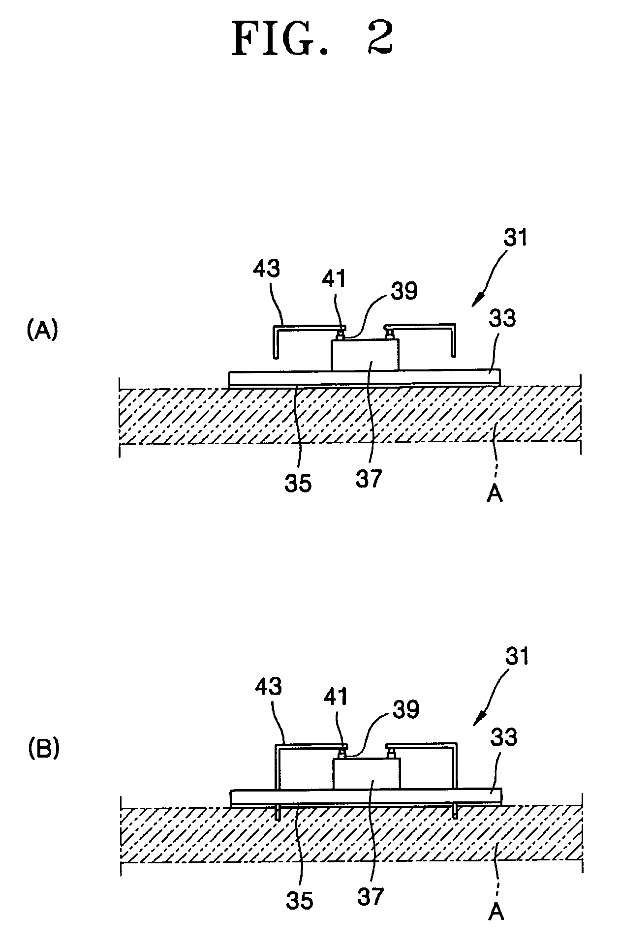
[0029]FIGS. 2A and 2B are elevation views depicting two embodiments of an ultra high frequency (UHF) radio frequency identification (RFID) tag 31 according to one aspect of the present invention.

[0030]Referring to FIG. 2A, the UHF RFID tag 31 includes a non-conductive substrate 33 of a certain thickness, a chip 37 being secured to a center of the substrate 33 and having a plurality of connecting bumps 39 (e.g., contacts, pads, pins,...


PUM


Abstract

An ultra high frequency (UHF) radio frequency identification (RFID) tag and a method of manufacturing the tag are provided. The tag includes a substrate, a chip attached to the substrate and having a plurality of bumps for connecting a circuit formed therein with an external, and at least one UHF antenna extended in a longitudinal direction and responding to ultra high frequency transferred from the external, at least one end of the UHF antenna connected to the bump, and one portion of the antenna fixed to the substrate. Also, the method includes a) process of fixing a chip having a plurality of bumps to an upper surface of a substrate, b) process of installing a cutter between the bumps such that a blade portion of the cutter is placed at a certain height from the substrate, and c) process of installing a UHF antenna by lowering the UHF antenna having an extended portion to the cutter, with the antenna being positioned in a direction perpendicular to the blade portion, cutting the extended portion of the antenna by the cutter, and continuously lowering the antenna until a cut end of the antenna is connected to the bump. Since the UHF RFID tag employs a plurality of short UHF antennas instead of a loop-type antenna, the tag is integrated as much as it is required, due to a small volume, and a process of bonding the antenna to a chip is rapidly and easily performed.

Description

CROSS-REFERENCE TO RELATED PATENT APPLICATIONS[0001]This application claims the benefit of Korean Patent Application No. 10-2004-0092270, filed on Nov. 12, 2004, in the Korean Intellectual Property Office, the disclosure of which is incorporated herein in its entirety by reference.BACKGROUND OF THE INVENTION[0002]1. Field of the Invention[0003]The present invention relates to an ultra high frequency (UHF) radio frequency identification (RFID) tag and a method of manufacturing the same.[0004]2. Description of the Related Art[0005]An RFID tag includes circuitry (e.g., a microchip) for storing various data and an antenna that is connected to the circuitry for inputting the data or transmitting the stored data to a reader. The RFID tag is used with the reader that receives a signal transmitted from the antenna (i.e., backscatter) and sends the signal to a dedicated computer to enable an operator to obtain and analyze the RFID tag's data.[0006]Various data stored on the RFID tag is read ...

Claims


Application Information

Patent Timeline
Patent Type & Authority Patents(United States)
IPC IPC(8): G08B13/14
CPCG06K19/07749G06K19/07779G06K19/07783H01Q1/2208H01Q9/26H01Q1/2225G06K19/07
Inventor KWAK, JAE-HYUNLIM, SE-JINKIM, SOO-HO
Owner HANWHA TECHWIN CO LTD
Learn More