
4 dimensional magnetic resonance imaging

a magnetic resonance imaging and 4 dimensional technology, applied in the field of 4 dimensional magnetic resonance imaging, can solve the problems of reducing the use value of nmr as a high resolution body imager, shortening the recording time, and increasing bandwidth and nois

Inactive Publication Date: 2008-06-03
MILLS RANDELL L
View PDF27 Cites 44 Cited by
  • Summary
  • Abstract
  • Description
  • Claims
  • Application Information

AI Technical Summary

Benefits of technology

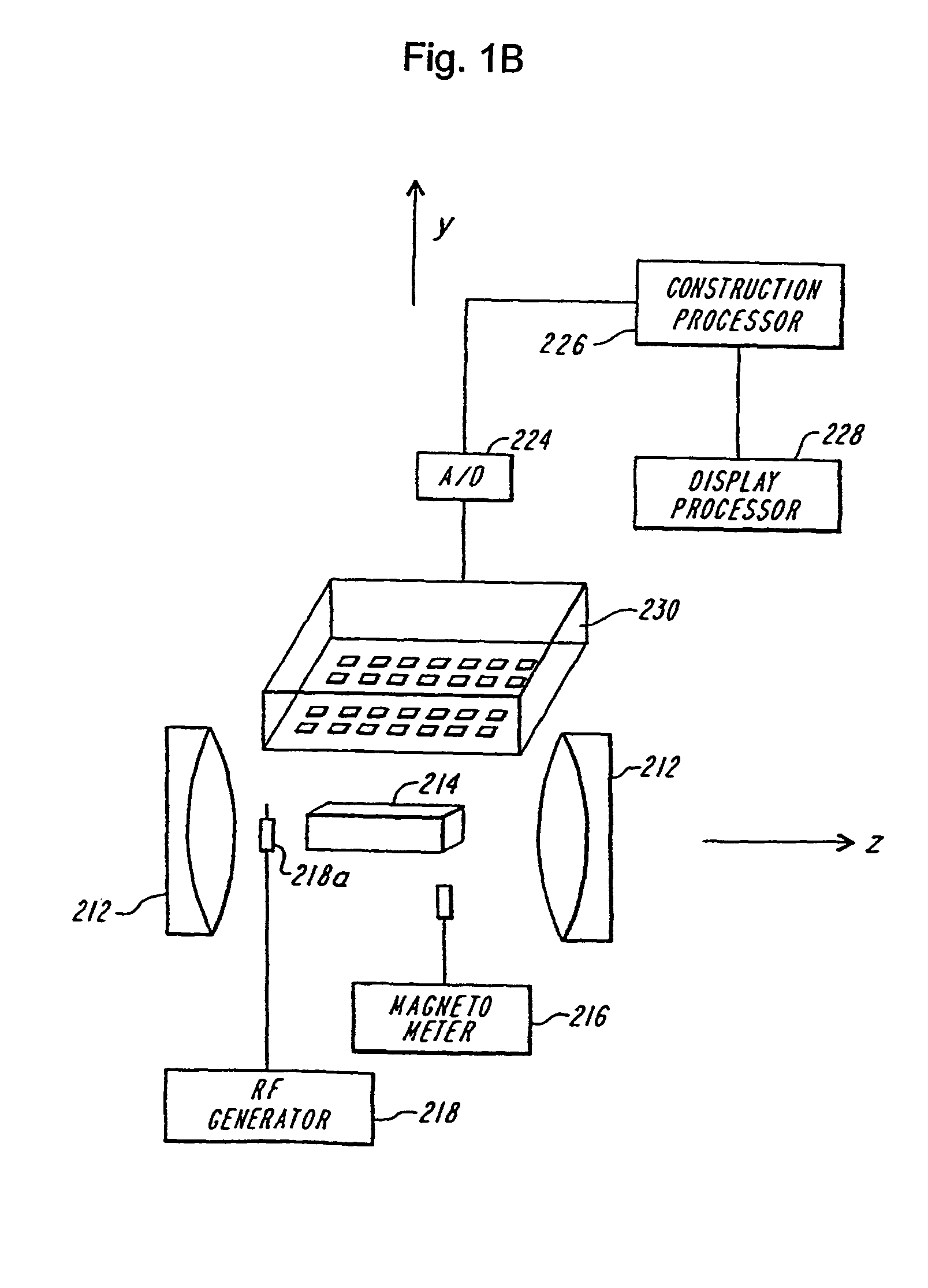
[0008]A NMR image is obtained of a magnetized body from a three-dimensional map of the intensity variation of the NMR signal produced by each voxel of the magnetized body, and detected over a three-dimensional volume of space external to the body, herein referred to as the “sample space.” The data is acquired over three spatial directions plus time. In an embodiment, the NMR signals are detected over a three dimensional detector array as a function of time. The NMR signals may be sampled at least at the Nyquist rate, i.e., at a rate that is twice the highest temporally frequency of the NMR signal and twice the highest spatial frequency the Fourier transform of the NMR image of the phantom. Sampling at the Nyquist rate or higher allows the spatial variations of the external NMR signal to be acquired.

Problems solved by technology

But long NMR relaxation times, a parameter based on how rapidly excited nuclei relax, have prevented NMR from being of utility as a high resolution body imager.
The most severe limitation of NMR technology is that for spin echo imaging n, the number of free induction decays (“FIDs”), a nuclear radio frequency energy emitting process, must equal the number of lines in the image.
The echo-planar technique requires shorter recording times with a concomitant increase in bandwidth and noise.
Both methods compensate for decreased SNR by increasing the voxel size with a concomitant decrease in image quality.
Physical limitations of these techniques render obtaining high resolution, high contrast vascular images impractical.

Method used


Image

  • 4 dimensional magnetic resonance imaging
  • 4 dimensional magnetic resonance imaging
  • 4 dimensional magnetic resonance imaging

Examples


Embodiment Construction

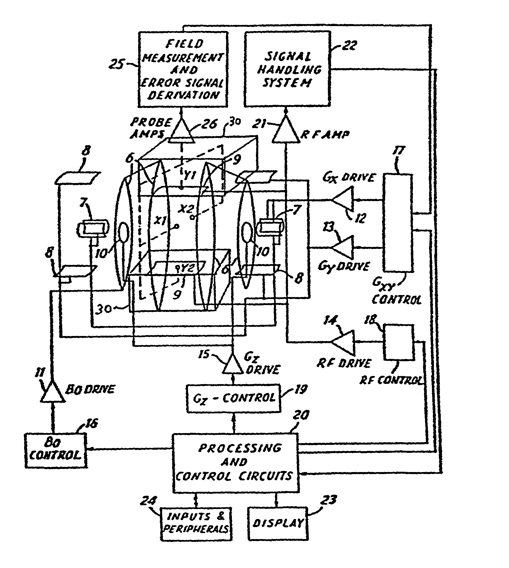
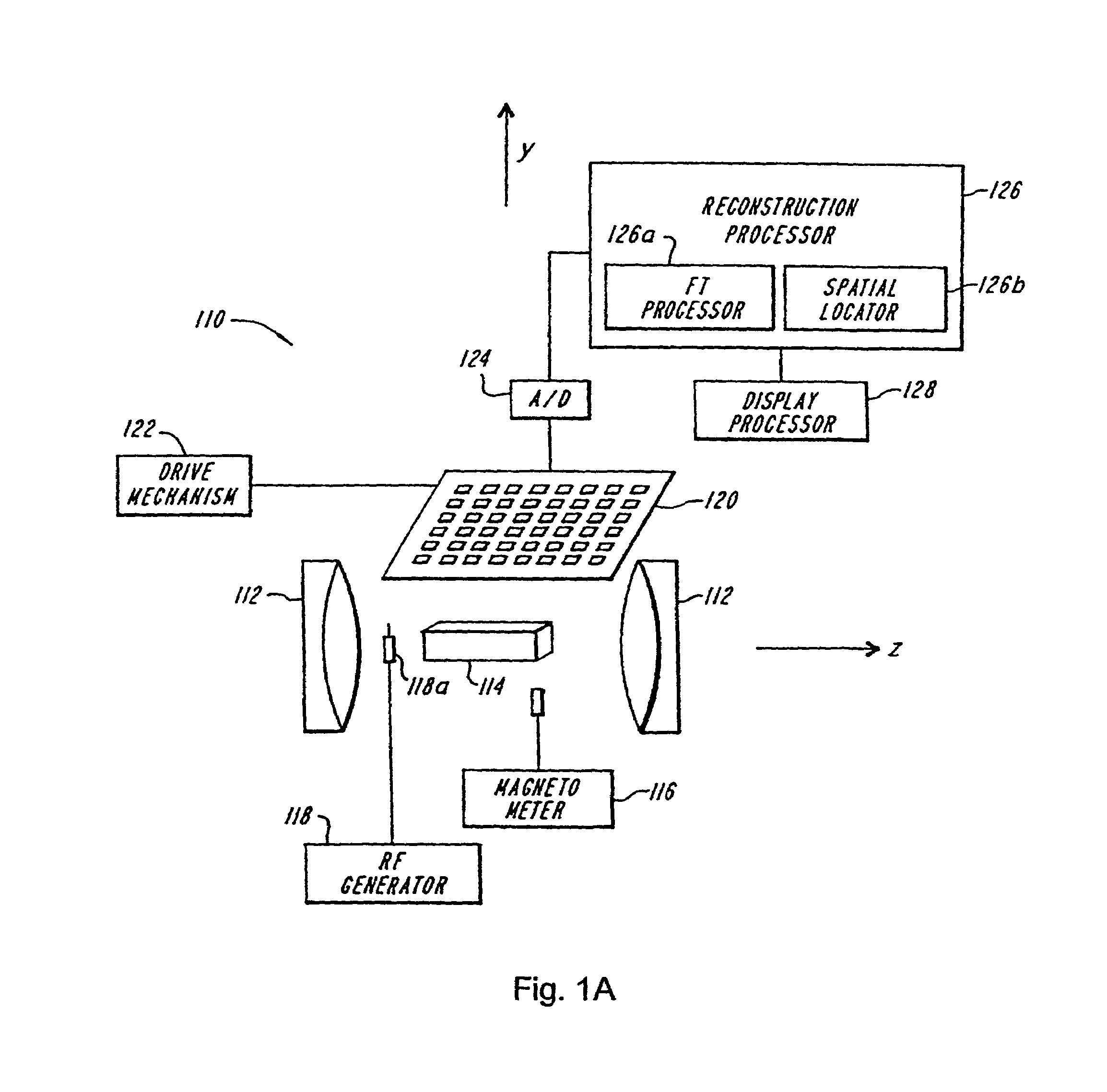
[0065]An exemplary embodiment of a nuclear magnetic resonance (4D-MRI apparatus 110 according to the teachings of the present invention is shown in FIG. 1a. The apparatus 110 includes a magnet 112, such as a superconducting magnet, that provides a primary or magnetizing field, to magnetize a body 114 to be imaged. A magnetometer 116 determines the primary or magnetizing field in the volume to be occupied by the body, i.e., in the image space, in the absence of the body. One practice of the invention utilizes a magnetometer that employs NMR of protons in water for determining the primary radiation field at multiple points in the image space. In an embodiment, the primary field is uniform as recorded by magnetometer 116.

[0066]A radiation source 118, such as a radio frequency generator, applies an RF pulse to the body in combination with RF antennae 118a when the body is placed in the magnetic field, to excite and thereby polarize selected nuclei of the body. The excited nuclei emit an...


PUM


Abstract

Provided are apparatus and methods for forming a multidimensional image of inanimate or animate objects which utilize a magnetization source (112) to magnetize a volume of an object to be imaged, a radiation source (118) for applying a radiation field to the object to be imaged, an output signal detector (120) for producing output signals in response to the secondary radiation at a plurality of spatial locations outside of the object as a function of time, processors (126, 126a and 126b) for determining a plurality of Fourier components, for associating the Fourier components due to each voxel (14) by phase, and for converting each set of components into a voxel location, and an image processor (128) for producing an image.

Description

[0001]This application claims priority to U.S. provisional application Ser. No. 60 / 226,667, filed on Aug. 22, 2000, the complete disclosure of which is incorporated herein by reference.FIELD OF THE INVENTION[0002]This invention relates to method and apparatus for imaging an object, such as a body. More particularly, the invention provides high resolution, real-time images in 4 dimensions with little or no deterioration from motion artifact.BACKGROUND OF THE INVENTION[0003]Nuclear Magnetic Imaging (NAMR) which is commonly called magnetic resonance imaging(MRI) entails 1.) magnetizing a volume with a constant primary magnetic field in a z-direction, 2.) providing a gradient along the axis of the z-directed field to select a slice in the xy-plane, the plane perpendicular to the direction of the primary field, 3.) providing electromagnetic radiation resonant with the Larmor frequency of protons in the slice, 4.) providing a pulse of resonant electromagnetic radiation to flip the magneti...

Claims


Application Information

Patent Timeline
IPC IPC(8): G01V3/00G01R33/54
CPCG01R33/482
Inventor MILLS, RANDELL L.
Owner MILLS RANDELL L
Learn More