
Fuel vapor release suppression system for fuel tank

a technology of fuel tank and suppression system, which is applied in the direction of liquid fuel feeders, machines/engines, combustion air/fuel air treatment, etc., can solve the problems of fuel vapor not being liquefied, power consumption of cooling system imposing a burden on the vehicle battery, etc., and achieve the effect of liquefying fuel vapor

Inactive Publication Date: 2008-06-03
HONDA MOTOR CO LTD
View PDF7 Cites 8 Cited by
  • Summary
  • Abstract
  • Description
  • Claims
  • Application Information

AI Technical Summary

Benefits of technology

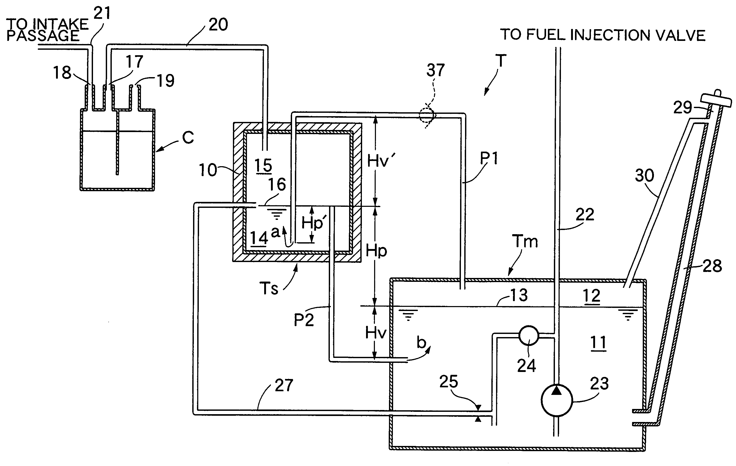
The present invention relates to a fuel vapor release suppression system for a fuel tank. The system includes a main tank, a sub tank, a communication passage for providing communication between the main tank and the sub tank, a canister, and a charge passage for providing communication between the sub tank and the canister. The system is designed to effectively liquefy fuel vapor generated in the fuel tank regardless of ambient air temperature. The system works by providing a gaseous mixture of air and fuel vapor in the gas-phase portion of the main tank, which enters the liquid-phase portion of the sub tank through a first communication passage. When the temperature of the main tank increases, the number of moles of the gaseous mixture decreases, causing the fuel vapor in the sub tank to liquefy and enter the gas-phase portion of the main tank through a second communication passage. This process accelerates the liquefaction of fuel vapor in the sub tank and allows for faster response to changes in fuel vapor pressure. The system also includes a check valve to prevent fuel vapor from flowing back into the main tank, ensuring efficient liquefaction in the sub tank.

Problems solved by technology

In this conventional arrangement, fuel vapor generated in the main tank can be liquefied in the sub tank when the temperature of the sub tank is lower than that of the main tank, but the fuel vapor cannot be liquefied when the temperature of the sub tank is higher than that of the main tank.
Therefore, in order to enable constant fuel vapor liquefaction, the temperature of the sub tank is required to be lowered by using a cooling device, leading to a problem that the power consumed by the cooling system imposes a burden on the vehicle battery.

Method used


Image

  • Fuel vapor release suppression system for fuel tank
  • Fuel vapor release suppression system for fuel tank
  • Fuel vapor release suppression system for fuel tank

Examples


first embodiment

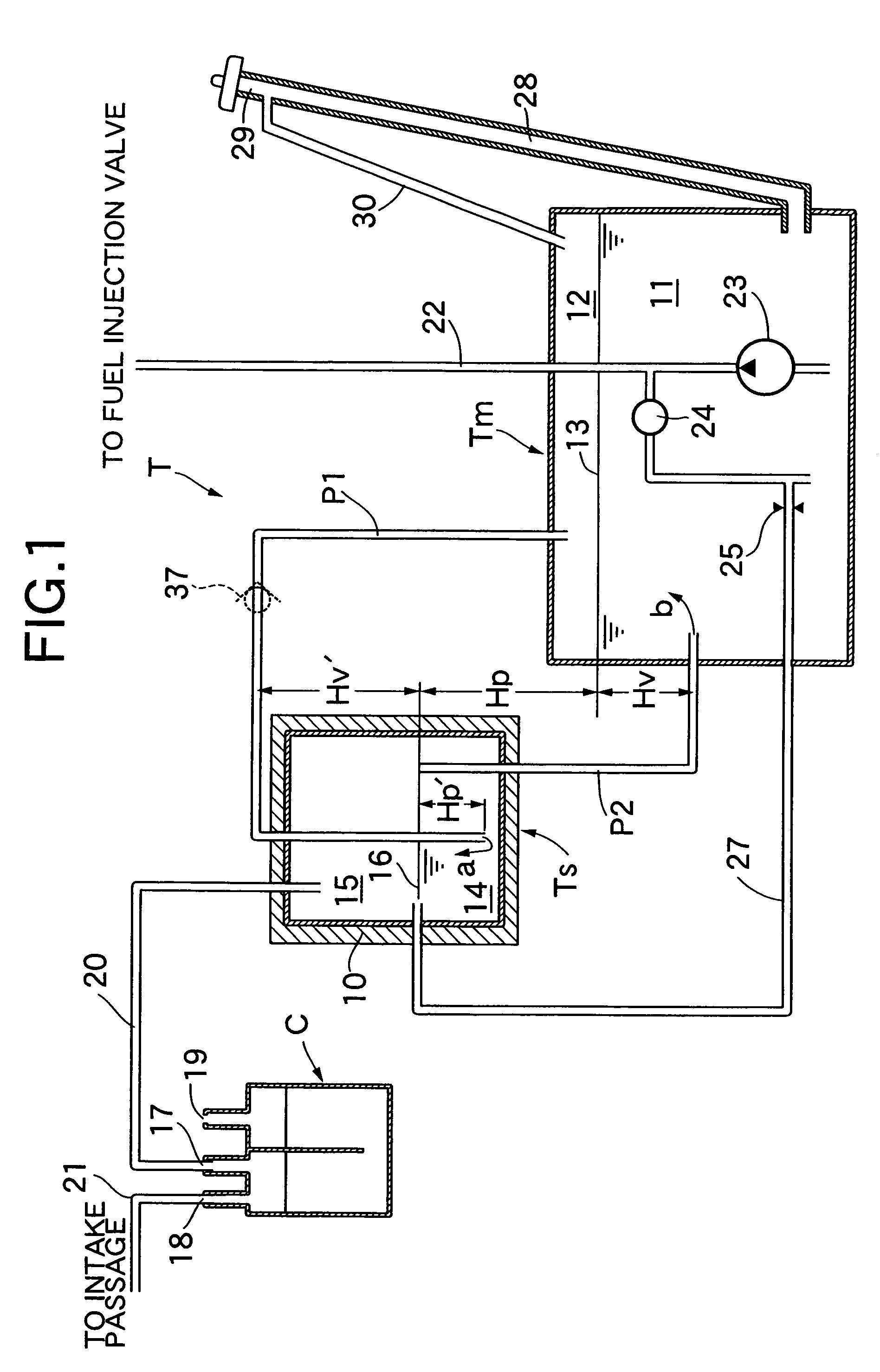
[0046]FIG. 1 shows the present invention. A fuel tank T of an automobile includes a main tank Tm and a sub tank Ts. The sub tank Ts, having a volume smaller than that of the main tank Tm, is disposed at a position higher than the main tank Tm. The periphery of the sub tank Ts is covered by a heat-insulating material 10. The interior of the main tank Tm is divided into a liquid-phase portion 11 filled with fuel and a gas-phase portion 12 filled with fuel vapor. When a fuel level 13 in the main tank Tm changes due to replenishment or consumption of fuel, the volume of the liquid-phase portion 11 and the volume of the gas-phase portion 12 change. The interior of the sub tank Ts is divided into a liquid-phase portion 14 filled with fuel and a gas-phase portion 15 filled with fuel vapor. A fuel level 16 in the sub tank Ts is basically constant. The gas-phase portion 12 of the main tank Tm and the liquid-phase portion 14 of the sub tank Ts are connected via a first communication passage P...

second embodiment

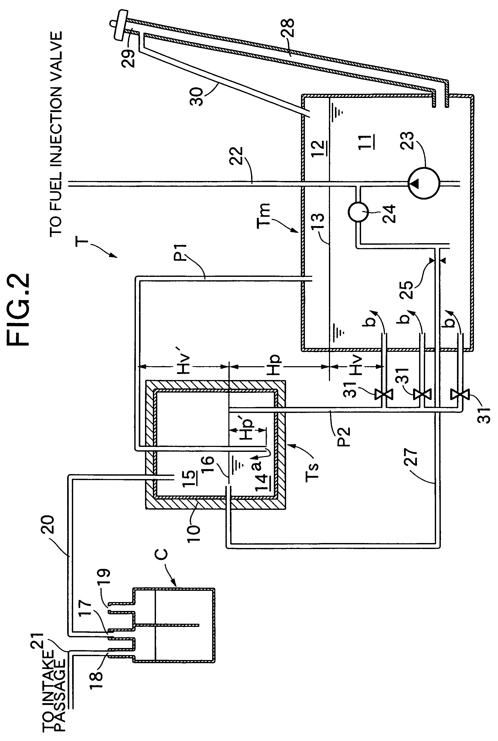
[0070]the present invention is now described by reference to FIG. 2.

[0071]As described in the first embodiment, Hv2 while preventing fuel from flowing from the sub tank Ts back to the main tank Tm via the first communication passage P1. However, since the height Hv changes in response to the fuel level 13 of the main tank Tm going up and down, it is difficult to constantly establish Hv

[0072]That is, in order to supply fuel vapor from the gas-phase portion 15 of the sub tank Ts to the liquid-phase portion 11 of the main tank Tm via the second communication passage P2, it is desirable to lower the position of the opening portion of the second communication passage P2 in the main tank Tm as much as possible. However, lowering the position of the opening portion increases the height Hv, thus making it difficult to establish Hv2 in the main tank Tm is raised, there is a problem that the opening portion is exposed above the fuel level 13 when the fuel level 13 goes down, and fuel vap...

third embodiment

[0074]the present invention is now described by reference to FIG. 3.

[0075]In the first and second embodiments, the sub tank Ts is disposed outside the main tank Tm, but in the third embodiment a sub tank Ts is disposed within a main tank Tm. Disposing the sub tank Ts within the main tank Tm reduces the overall size of the entire fuel tank T, reduces the number of steps in assembling the fuel tank T to a vehicle body, and improves the degree of freedom in the layout. Further, since the sub tank Ts, disposed within the main tank Tm, is not susceptible to the influence of the ambient air temperature, it is not necessary to attach the heat-insulating material 10 to the sub tank Ts, as shown in the first and second embodiments.

[0076]Furthermore, it is necessary to make the highest portion of the first communication passage P1 relatively high in order to secure a sufficient height Hv′, leading to a problem that the first communication passage P1 inevitably becomes long. To solve such a pr...


PUM


Abstract

In a fuel vapor release suppression system for a fuel tank, a main tank and a sub tank communicate with each other, and the sub tank and a canister communicate with each other. When the main tank has a higher temperature, fuel vapor of the main tank is supplied to the sub tank where the fuel vapor is liquefied. When the main tank has a lower temperature, fuel vapor of the sub tank is supplied to the main tank. At this time, low concentration fuel vapor is supplied from the canister to the main tank, thereby accelerating generation of fuel vapor corresponding to sub tank fuel vapor pressure, so that the sub tank fuel vapor pressure decreases. Therefore, liquefaction is accelerated in the sub tank when the main tank temperature increases. Thus, fuel vapor generated in a fuel tank is effectively liquified irrespective of ambient air temperature.

Description

CROSS-REFERENCE TO RELATED APPLICATIONS[0001]The present invention claims priority under 35 USC 119 based on Japanese patent application No. 2005-376027, filed on Dec. 27, 2005. The subject matter of this priority document is incorporated by reference herein.BACKGROUND OF INVENTION[0002]1. Field of the Invention[0003]The present invention relates to a fuel vapor release suppression system for a fuel tank, in which a main tank and a sub tank communicate with each other via a communication passage, and the sub tank and a canister communicate with each other via a charge passage.[0004]2. Description of Related Art[0005]Japanese Patent Publication No. 3659005 discloses an automobile fuel tank arrangement wherein a sub tank is provided separately from a main tank, and is placed in a low temperature environment as compared with the main tank. In this arrangement, fuel vapor is supplied from a gas-phase portion of the main tank, having a higher temperature, to a liquid-phase portion of the...

Claims


Application Information

Patent Timeline
Patent Type & Authority Patents(United States)
IPC IPC(8): F02M17/20F02M17/22
CPCF02M25/089F02M37/0058F02M37/0088F02M37/10Y10T137/86196Y10T137/86212
Inventor HATANO, GAKUHIDANO, KOICHIKITAMOTO, MASAKAZUHIDAI, SHIGEOUHARA, SHOJIKITAMURA, HIROSHIIMAMURA, TAKAHIRO
Owner HONDA MOTOR CO LTD
Learn More