
Reconfigurable auditory-visual display

a visual display and reconfigurable technology, applied in the direction of signalling systems, instruments, computing, etc., can solve the problems of not allowing the operator to quickly (re)direct attention, not allowing the operator to fix the operator's attention, and not providing information on the present location, so as to improve the intelligibility of speech and facilitate the monitoring of visual channels

Inactive Publication Date: 2008-05-27
NASA
View PDF8 Cites 255 Cited by
  • Summary
  • Abstract
  • Description
  • Claims
  • Application Information

AI Technical Summary

Benefits of technology

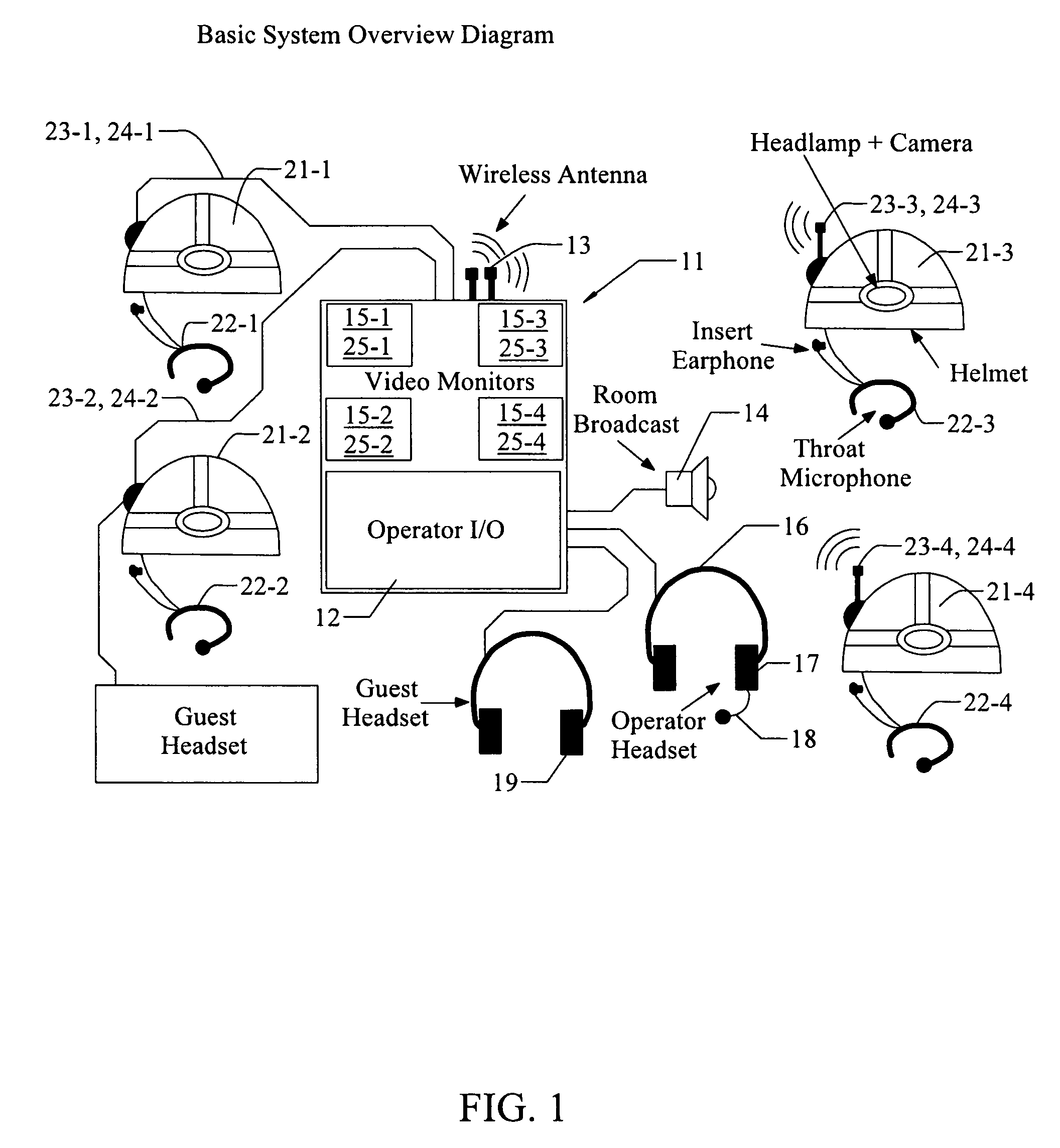
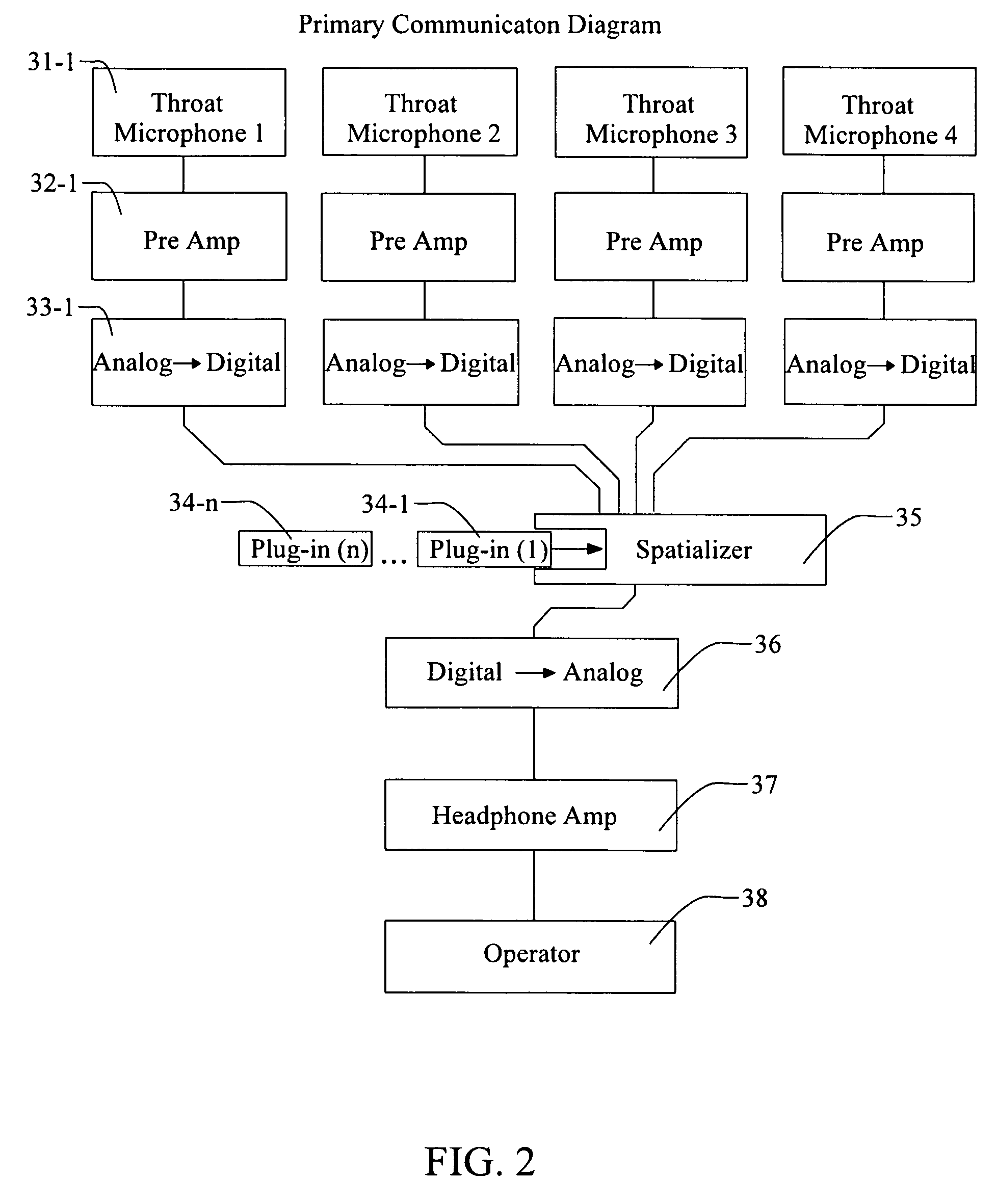
[0005]These needs are met by the invention, which provides a method and system that allows auditory and visual monitoring of multiple, simultaneous communication channels at a centralized command post (“local control center”) with enhanced speech intelligibility and ease of monitoring visual channels; visual feedback as to which channel(s) has active audible communications; and orientation information for each of N monitored communicators (N≧1). Each monitored communicator wears a hard hat equipped with lighting according to O.S.H.A. regulations, headphone, throat microphone and visual image transmitter (e.g., a camera). The local control center, which may be embodied within a hardened laptop computer or equivalent device, includes software for modifying input audio signals via compression and binaural (three-dimensional audio) signal processing, combining these audio signals with visual video, location, angular orientation and situational awareness information, and presenting the audio signals from perceived locations that are spatially separated.
[0009]The invention creates a multi-model communications environment that increases the situational awareness for the operator (controller). Situational awareness is increased by a number of innovations such as spatially separating each voice communication channel, allowing a single voice channel to be prioritized while still allowing other channels to be monitored. This allows the controller to view real time video from each of the controlled communicators, allowing sensor data from these communicators to be electronically collected separately, rather than being collected over the voice channel. The approach also provides an interface for the operator to record and transmit event data. In addition, each communications channel is equipped with a video indicator that allows the operator to determine who is speaking and from which communication channel the signal is being received.
[0011](1) A local control center in a search and rescue or monitoring operation often requires one operator with a portable communication device to focus attention simultaneously, both visually and audibly, on as many as four different personnel at once. The operator must be able to focus on a specific communicator without sacrificing active monitoring (e.g., in the background) of other communicators. By supplying a coordinated spatial display of visual and auditory information, greater ease of segregation of information (auditory, visual, state situation) may be conveyed.

Problems solved by technology

However, this approach treats all such signals substantially equally and does not permit fixing the operator's attention on a display that requires sustained attention for an unpredictable time interval.
This approach also does not permit the operator to quickly (re)direct attention to, and assign temporary priority to, two or more communicators, out of the sequence set by the time sharing procedure.
This approach, by itself, does not provide information on the present location, present angular orientation and present environment of the communicator.

Method used


Image

  • Reconfigurable auditory-visual display
  • Reconfigurable auditory-visual display
  • Reconfigurable auditory-visual display

Examples


Embodiment Construction

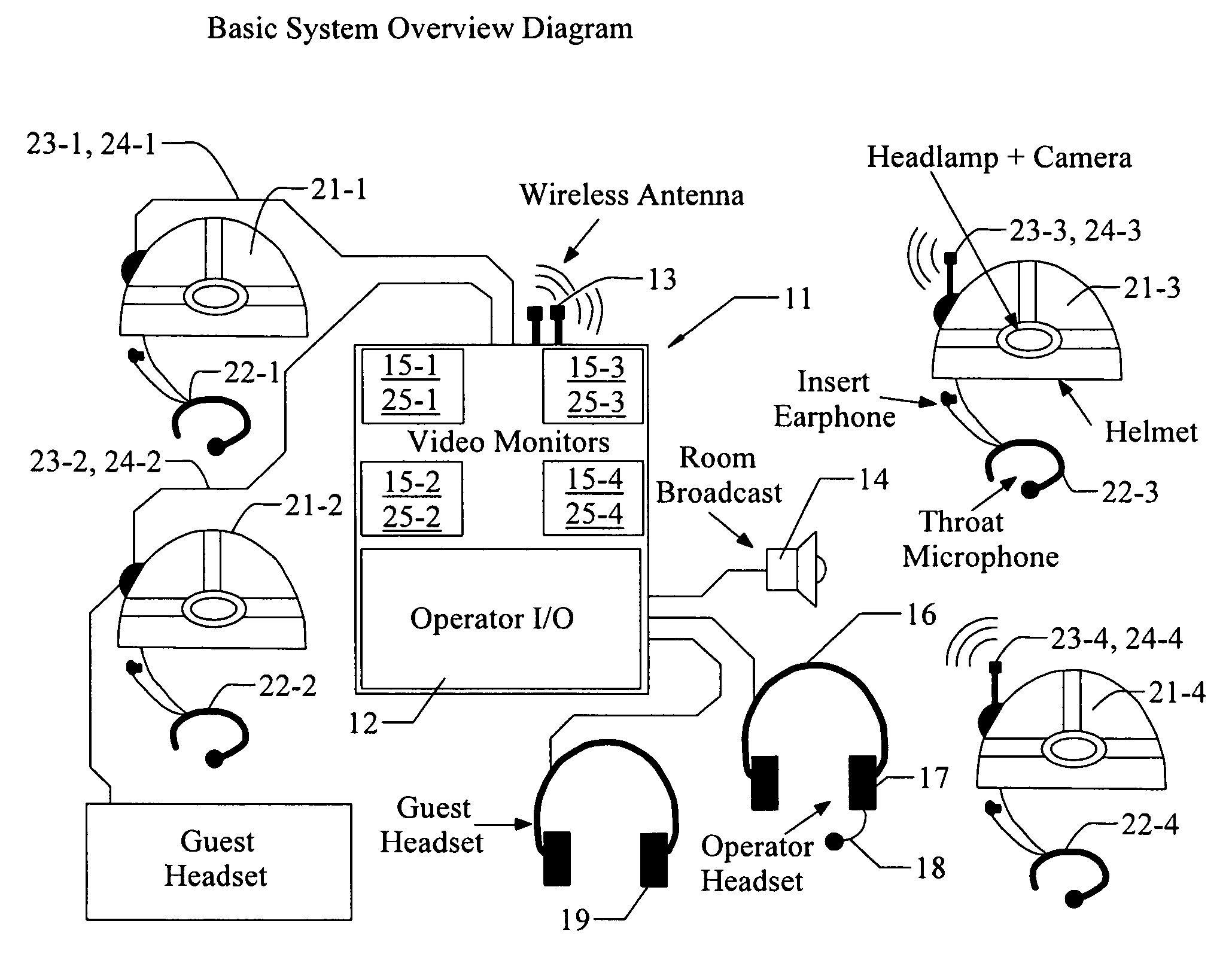
[0021]FIG. 1 schematically illustrates an operator interface 11 with several communicators (here, four), spaced apart from the operator, according to the invention. The operator interface 11 includes an operator I / O module 12, connected to a wireless, N-channel antenna 13, an optional room audio broadcast module 14, and a plurality of video monitors, 15-n (n=1, . . . , N; here, N=4), where the monitor 15-n receives and displays visual images associated with a helmet 21-n worn or carried by communicator no, n. The operator is connected to the operator interface by an operator headset 16, which includes operator headphones 17 and an operator microphone 18 that provides broadcast or multi-cast audio signals for transmission over the N-channel transmission system to one, more or all of the N communicators. Optionally, the operator interface also includes a guest headset 19, having headphones only, for use by a guest to monitor, with no audible input, audio information received by the op...


PUM


Abstract

System and method for visual and audible communication between a central operator and N mobile communicators (N≧2), including an operator transceiver and interface, configured to receive and display, for the operator, visually perceptible and audibly perceptible signals from each of the mobile communicators. The interface (1) presents an audible signal from each communicator as if the audible signal is received from a different location relative to the operator and (2) allows the operator to select, to assign priority to, and to display, the visual signals and the audible signals received from a specified communicator. Each communicator has an associated signal transmitter that is configured to transmit at least one of the visual signal and the audio signal associated with the communicator, where at least one of the signal transmitters includes at least one sensor that senses and transmits a sensor value representing a selected environmental or physiological parameter associated with the communicator.

Description

ORIGIN OF THE INVENTION[0001]This invention was made, in part, by one or more employees of the U.S. government. The U.S. government has the right to make, use and / or sell the invention described herein without payment of compensation therefor, including but not limited to payment of royalties.FILED OF THE INVENTION[0002]This invention relates to analysis and display of signals representing location and angular orientation of a human's body.BACKGROUND OF THE INVENTION[0003]In many environments, a central operator communicates with, and receives visual signals and / or auditory signals from, two or more mobile or non-mobile communicators who are responding to, or relaying information on, one or more events in the field through a signaling channel associated (only) with that communicator. The event(s) may be a medical emergency or hazardous substance release or may be associated with continuous monitoring of a non-emergency situation. The visual and / or auditory signals may be displayed t...

Claims


Application Information

Patent Timeline
IPC IPC(8): G08B1/08
CPCG08B7/06
Inventor BEGAULT, DURAND R.ANDERSON, MARK R.MCCLAIN, BRYANMILLER, JOEL D.
Owner NASA
Learn More