Engine control system with mixed exhaust gas oxygen sensor types

a technology of exhaust gas and sensor type, which is applied in the direction of engine controllers, electric control, machines/engines, etc., can solve the problems of degrading temperature control, increasing the cost of adding sensors, and affecting the operation of the engine, so as to improve the stoichiometric operation, improve lean operation, and reduce the overall system cost

Active Publication Date: 2008-05-27
FORD GLOBAL TECH LLC
View PDF17 Cites 4 Cited by
  • Summary
  • Abstract
  • Description
  • Claims
  • Application Information

AI Technical Summary

Benefits of technology

[0006]In this way, it is possible to improve stoichiometric operation and reduce overall system cost since at least one switching type sensor is provided that can provide compensation to both cylinder groups. Further, it is possible to improve lean operation since at least one linear type sensor is provided that can also provide compensation to both cylinder groups. Finally, a decontamination cycle can be accurately controlled using both the linear and switching type sensor, since at least one of the oxygen rich gasses, or reductant rich gasses can be accurately measured via the linear sensor, and thus accurately limit the exothermic reaction (since the reaction will be limited by one of excess oxidants or excess reductants).

Problems solved by technology

However, the additional costs of adding sensors typically forces selection of a single sensor type for any given exhaust location, at least in some systems.
Further, these disadvantages can be exacerbated when the engine operates in various lean, stoichiometric, and decontamination modes.
Specifically, when performing decontamination cycles where some cylinder are operated with an oxygen rich exhaust, and other cylinders are operating with a reductant rich exhaust, degraded temperature control may be encountered (due to air-fuel ratio errors) that can degrade catalyst operation.

Method used


Image

  • Engine control system with mixed exhaust gas oxygen sensor types
  • Engine control system with mixed exhaust gas oxygen sensor types
  • Engine control system with mixed exhaust gas oxygen sensor types

Examples


Embodiment Construction

)

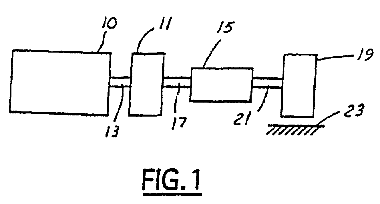
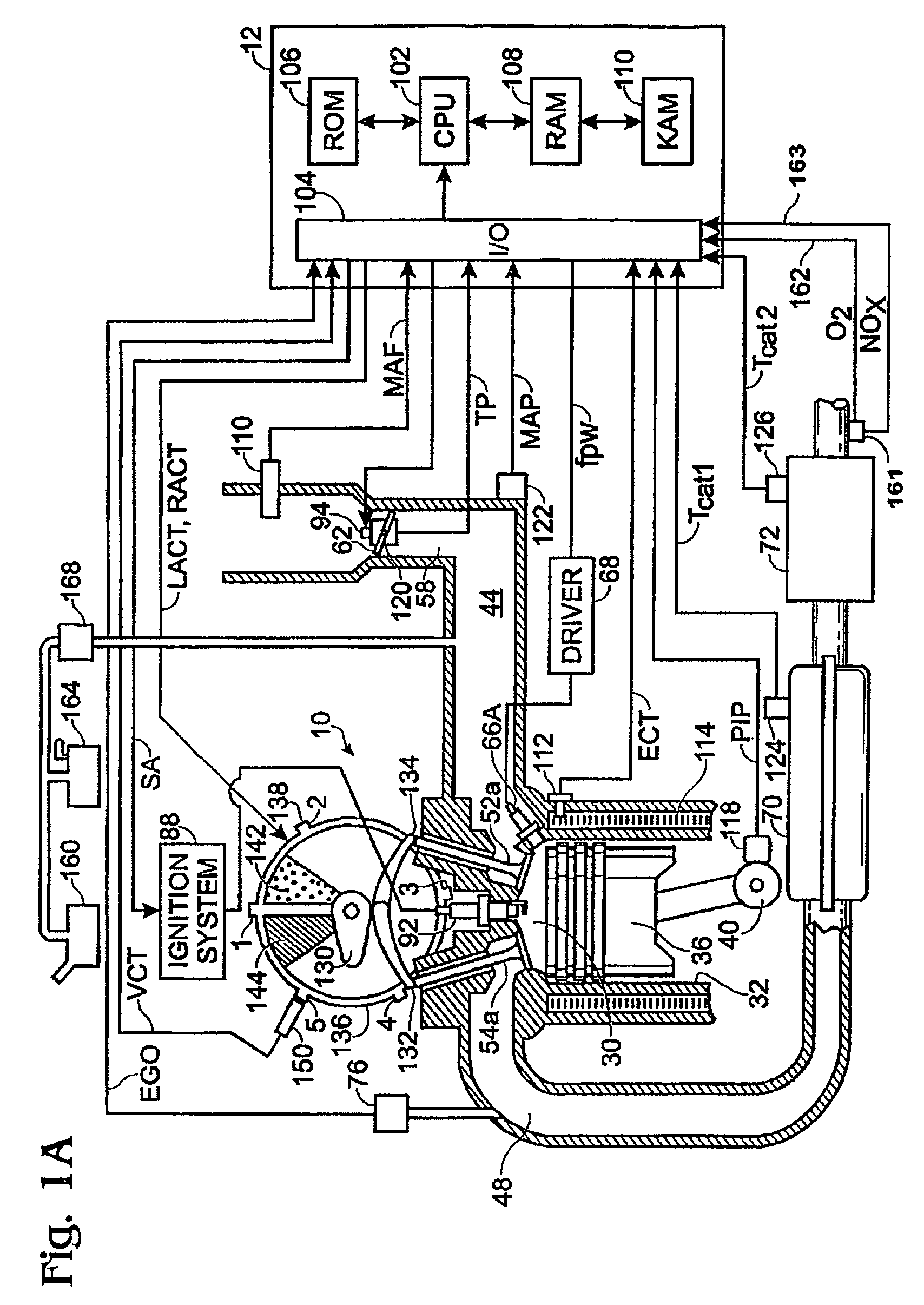
[0014]Referring to FIG. 1, internal combustion engine 10, further described herein with particular reference to FIGS. 1A and 1B, is shown coupled to torque converter 11 via crankshaft 13. Torque converter 11 is also coupled to transmission 15 via turbine shaft 17. Torque converter 11 has a bypass, or lock-up clutch (not shown) which can be engaged, disengaged, or partially engaged. When the clutch is either disengaged or partially engaged, the torque converter is said to be in an unlocked state. The lock-up clutch can be actuated electrically, hydraulically, or electro-hydraulically, for example. The lock-up clutch receives a control signal (not shown) from the controller, described in more detail below. The control signal may be a pulse width modulated signal to engage, partially engage, and disengage, the clutch based on engine, vehicle, and / or transmission operating conditions. Turbine shaft 17 is also known as transmission input shaft. Transmission 15 comprises an electronicall...


PUM


Abstract

A system for a vehicle traveling on the road is shown. The system includes a first cylinder; a second cylinder; a linear exhaust gas sensor coupled exclusively to said first cylinder; a switching exhaust gas sensor coupled exclusively to said second cylinder; and a controller configured to perform a decontamination cycle where one of said first cylinder and second cylinder produces a reductant rich exhaust and the other of said first and said second cylinder produces an oxygen rich exhaust, where an air-fuel ratio of one of said first and second cylinder is adjusted in response to said linear sensor.

Description

[0001]The present application is a continuation-in-part of U.S. patent application Ser. No. 10 / 794,494, filed on Mar. 5, 2004, now U.S. Pat. No. 7,0021,046, the entire contents of which are incorporated herein by reference for all purposes.BACKGROUND AND SUMMARY[0002]Internal combustion engines utilize feedback from exhaust gas oxygen sensors to maintain desire air-fuel ratio mixtures during combustion, at least under some conditions. Various types of exhaust gas oxygen sensors may be used, such as linear type sensors (sometimes referred to as UEGO sensors), and switching type sensors (sometimes referred to as EGO, or HEGO, sensors, depending on whether a heater is included).[0003]The inventors herein have recognized that under some conditions, it may be advantageous to utilize a switching type sensor, such as when operating about stoichiometry, as it may be possible to have a more accurate identification of stoichiometry through operating conditions and sensor aging. Further, it ma...

Claims


Application Information

Patent Timeline
Patent Type & Authority Patents(United States)
IPC IPC(8): F01N3/00F02M7/00
CPCF01N3/0814F01N3/0842F02D41/008F02D41/0275F01N13/011F02D41/1454F02D41/1456F01N13/009F02D41/1443
Inventor MAKKI, IMADKERNS, JAMESSMITH, STEPHEN
Owner FORD GLOBAL TECH LLC
Why Eureka
Try Eureka