
Disk drive with improved method for operating a thermal head fly-height actuator

a technology of thermal head and actuator, which is applied in the direction of magnetic recording, data recording, instruments, etc., can solve the problems of weak writability, higher than optimal flying height, and higher error rate of continuous multiple-sector write, so as to minimize the risk of head-disk contact, optimal head-disk spacing, and high power level

Active Publication Date: 2008-05-20
WESTERN DIGITAL TECH INC
View PDF20 Cites 39 Cited by
  • Summary
  • Abstract
  • Description
  • Claims
  • Application Information

AI Technical Summary

Benefits of technology

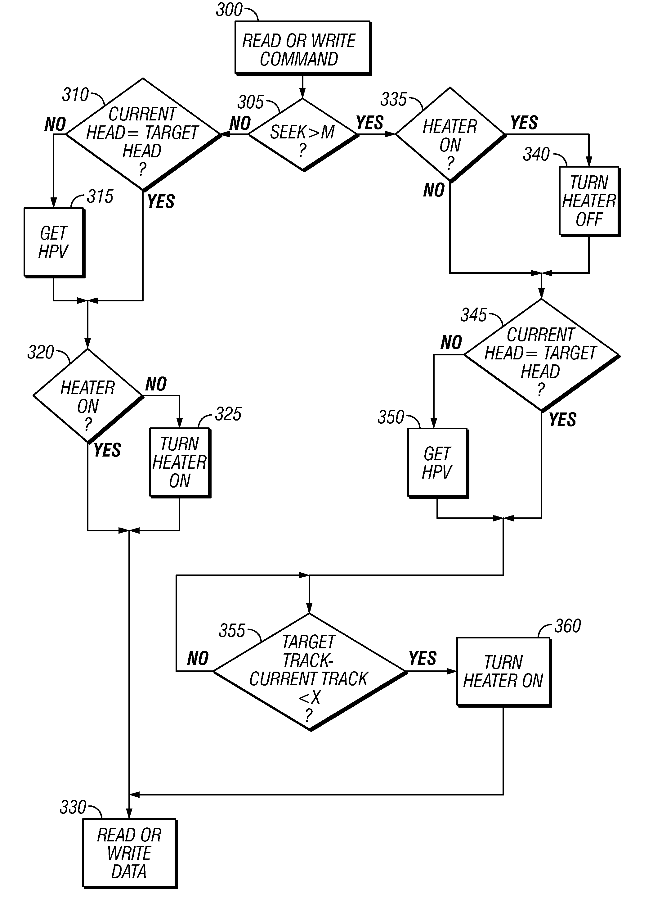
[0010]The invention is a disk drive with a thermal fly-height actuator and an improved method for operating the fly-height actuator. The fly-height actuator is controlled by a controller that includes a processor and associated memory that includes program instructions for executing the improved method of operation. The memory also includes registers or look-up tables for read heater power values (HPVs) and write HPVs, with each HPV being associated with a read/write head and a band of data tracks. As part of the improved operating method, the heater may be deactivated during a seek, depending on the length of the seek, to minimize the risk of head-disk contacts. When a write command is received, the controller applies an HPV to the heater to pre-heat the write head prior to writing the i...

Problems solved by technology

Thus when conventional thermal fly-height control is applied during writing the first few data sectors of a continuous multiple-sector write may have a higher error rate than later-written data sectors because the write head is still at its ambient temperature and thus has no protrusion.
This results in a higher-than-optimal flying height over these initial data sectors and thus weaker writability.
Also, if the heater is activated during certain seeks (i.e., when the head is being moved from one data track to another data track), there may be a higher risk of head-disk contact, including head crashes that result in unrecoverable disk drive failure.

Method used


Image

  • Disk drive with improved method for operating a thermal head fly-height actuator
  • Disk drive with improved method for operating a thermal head fly-height actuator
  • Disk drive with improved method for operating a thermal head fly-height actuator

Examples


Embodiment Construction

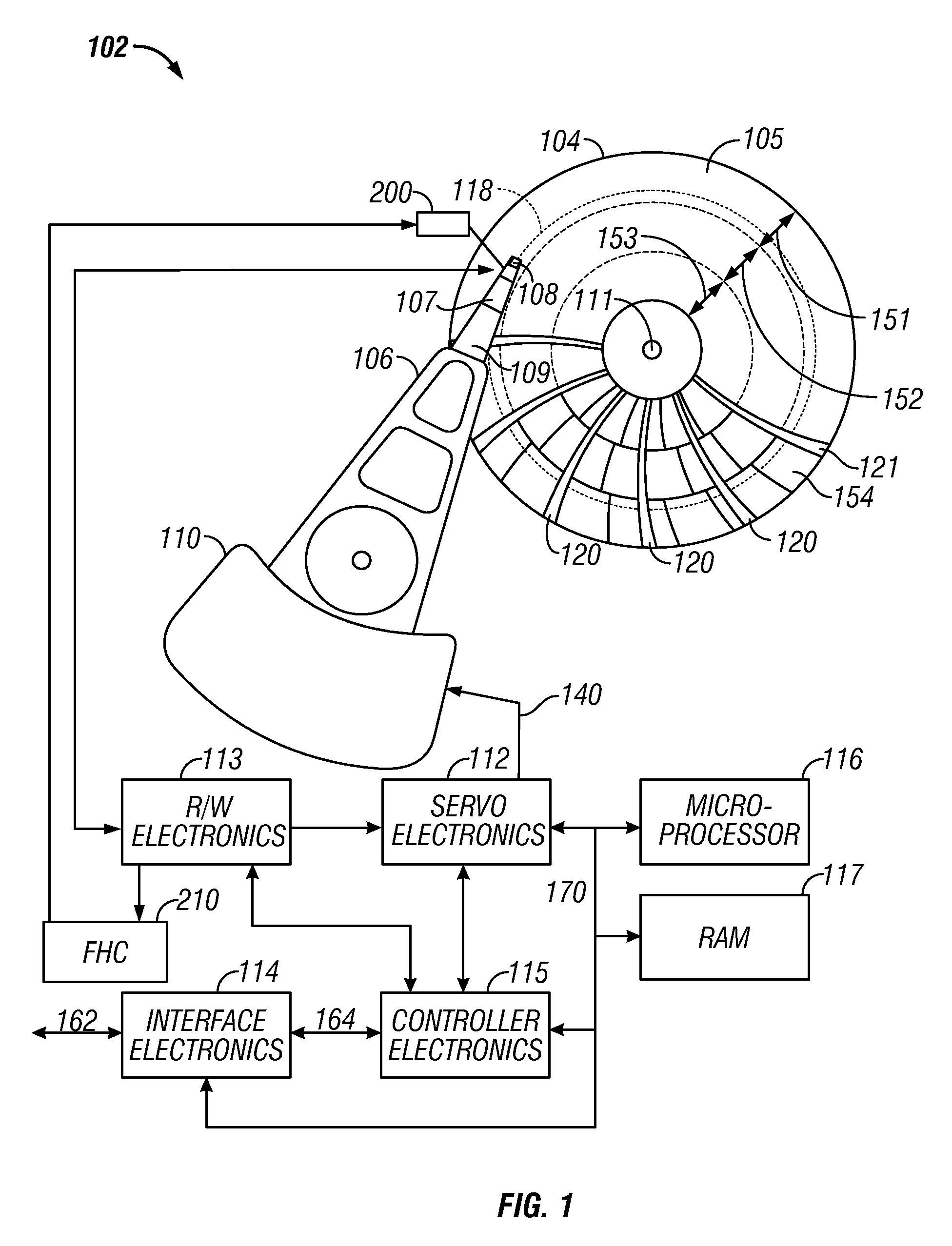
[0020]FIG. 1 is a block diagram of a conventional disk drive of the type usable with the present invention. The disk drive depicted is one that is formatted using a fixed-block “headerless” architecture with sector servo and zone-bit recording (ZBR), but the invention is applicable to disk drives using other types of data architectures and servo systems.

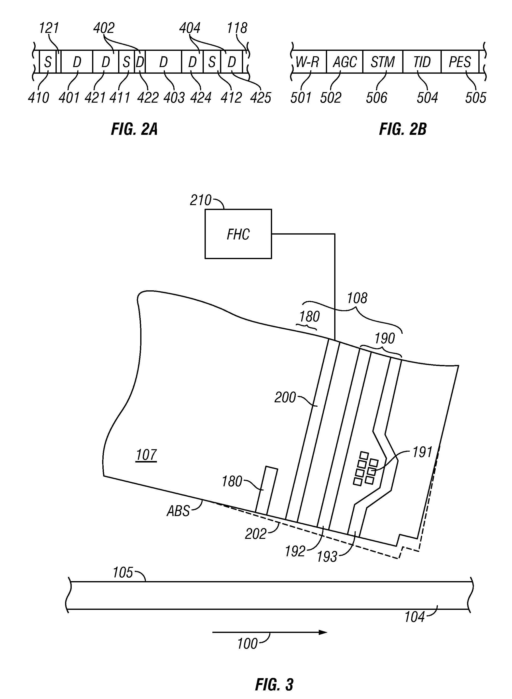
[0021]The disk drive, designated generally as 102, includes at least one data recording disk 104, a voice coil motor 110 actuator, an actuator arm 106, a suspension 109, a head carrier or slider 107, a data recording transducer 108 (also called a recording head or read / write head), servo electronics 112, read / write electronics 113, interface electronics 114, controller electronics 115, microprocessor 116, and RAM 117. The recording head 108 may be an inductive read / write head or a combination of an inductive write head with a magnetoresistive (MR) read head. The read / write 108 is typically located on a head carrier, such as an air-be...


PUM


Abstract

A disk drive has a resistive heater located near the read / write head as a thermal fly-height actuator and uses an improved method for operating the fly-height actuator. As part of the method, the heater may be deactivated during a seek to minimize the risk of head-disk contacts. When a write command is received, a level of heater power is applied to pre-heat the write head prior to writing the initial data sectors. This pre-heating heater power level may be higher than the power level used for writing. Then when writing commences, the lower power level is applied to the heater so the write head has the optimal head-disk spacing during the writing of all the data sectors, including the initial data sectors. Even though the heater may be deactivated during the seek the controller can initiate pre-heating during the last portion of the seek before the write head has reached the target track.

Description

BACKGROUND OF THE INVENTION[0001]1. Field of the Invention[0002]This invention relates to magnetic recording disk drives, and more particularly to disk drives that have a fly-height actuator for controlling the spacing between the read / write head and the disk.[0003]2. Description of the Related Art[0004]Magnetic recording hard disk drives use a read / write transducer or head mounted on a head carrier for reading and / or writing data to the disk. The head carrier is typically an air-bearing slider attached to an actuator arm by a suspension and positioned very close to the disk surface by the suspension. There are typically a stack of disks in the disk drive with a slider-suspension assembly associated with each disk surface in the stack.[0005]The separation or spacing between the head and the disk surface is called the fly-height. The slider has a disk-facing air-bearing surface (ABS) that causes the slider to ride on a cushion or bearing of air generated by rotation of the disk. The ...

Claims


Application Information

Patent Timeline
IPC IPC(8): G11B21/02
CPCG11B5/314G11B5/40G11B5/5547G11B5/6005G11B5/6064G11B5/607G11B5/3133G11B21/21G11B21/02G11B21/16
Inventor DIERON, ROELHATTORI, RYOHHEITAPATWARDHAN, SATYAJIT NEELKANTHWIEDERHOLT, CHRISTOPHER DAVID
Owner WESTERN DIGITAL TECH INC
Learn More