
RGBZ (red, green, blue, z-depth) filter system usable with sensor systems, including sensor systems with synthetic mirror enhanced three-dimensional imaging

Inactive Publication Date: 2008-05-20
MICROSOFT TECH LICENSING LLC
View PDF3 Cites 402 Cited by
  • Summary
  • Abstract
  • Description
  • Claims
  • Application Information

AI Technical Summary

Benefits of technology

[0019]In a second aspect, the invention provides an RGB-Z imaging system with the visual effect of a mirror to provide a user viewing an RGB image captured by the system with a sensation of depth. Preferably as the user's head moves relative to the displayed image, objects in the captured scene move proportionally to their distance from the system. When the RGB-Z system is used in a motor vehicle, for example, the result is to provide the user with more meaningful information as to objects in near proximity to the vehicle.

Problems solved by technology

But as a practical matter, in some applications it may simply not be feasible to implement beam splitting.
Detection of NIR or IR energy is a bit more complicated.
But dye filters cannot readily be implemented with narrowly defined pass bands.
A typical pass band for a dye filter might be about 100 nm or greater, with typically poor frequency roll-off characteristics.
But the sloppy characteristics associated with bulk filters does not lend such filters to use with Z pixels, which pixels require a very narrow bandwidth, e.g., about 30 nm.
But as the filter specification is generally silent as to transmission characteristics in the non critical 400 nm to 700 nm range, such filters typically pass optical energy in that wavelength band and are not suitable for use with systems such as shown in FIGS. 1A and 1B.

Method used


Image

  • RGBZ (red, green, blue, z-depth) filter system usable with sensor systems, including sensor systems with synthetic mirror enhanced three-dimensional imaging
  • RGBZ (red, green, blue, z-depth) filter system usable with sensor systems, including sensor systems with synthetic mirror enhanced three-dimensional imaging
  • RGBZ (red, green, blue, z-depth) filter system usable with sensor systems, including sensor systems with synthetic mirror enhanced three-dimensional imaging

Examples


Embodiment Construction

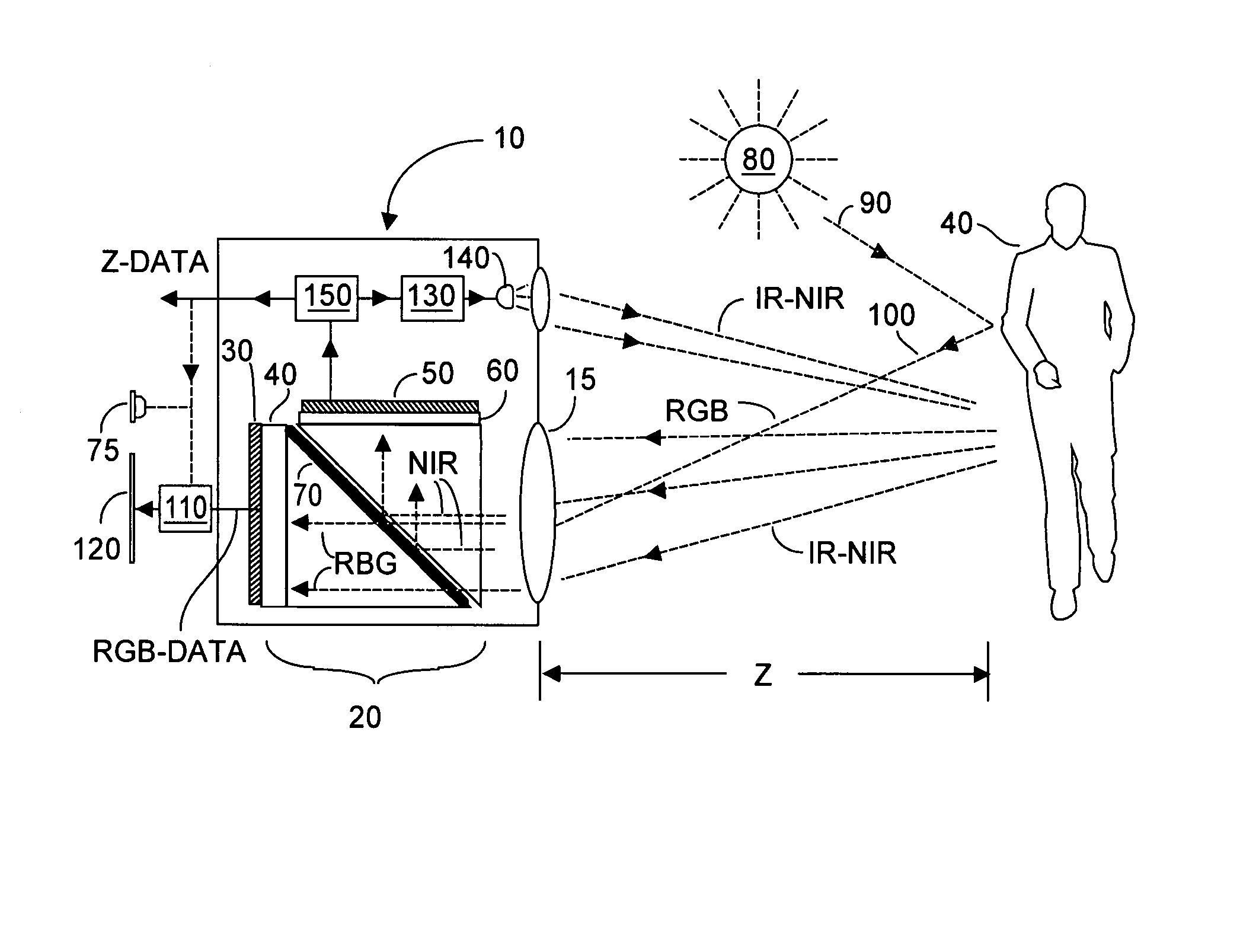
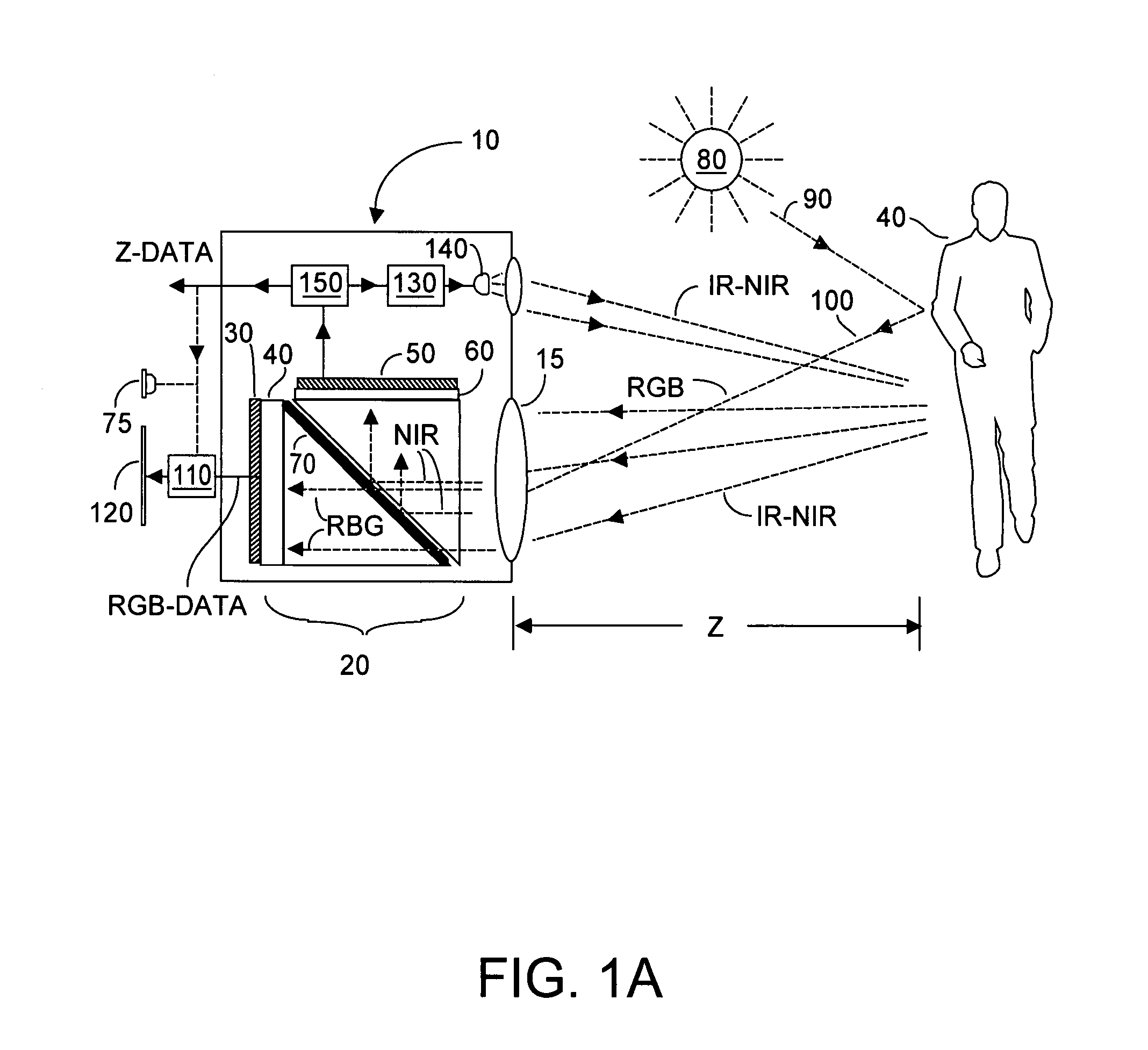
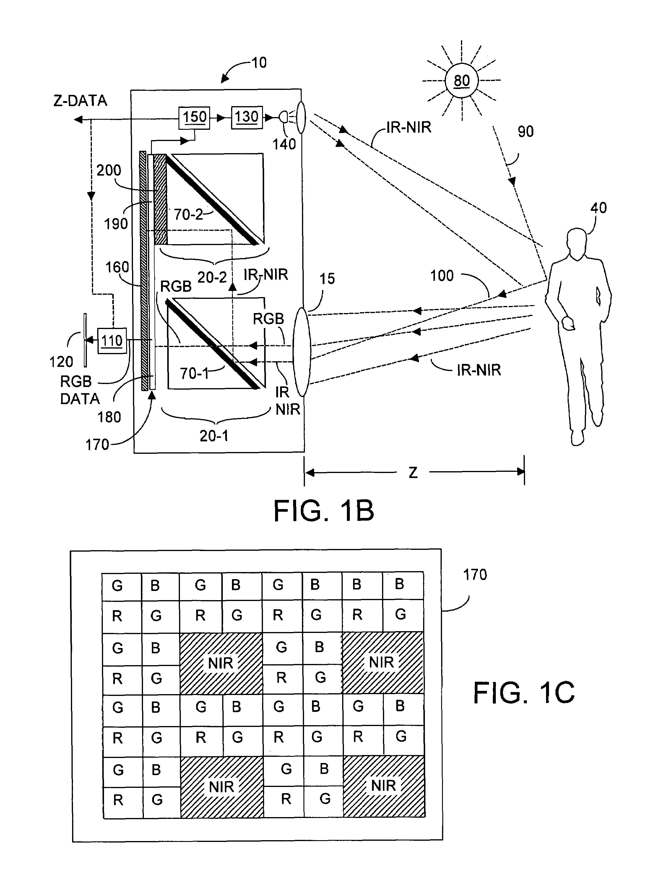
[0038]In one aspect, embodiments of the present invention provide a method and system for implementing an RGB-Z imaging system having a global optical path common to R, G, B, and Z pixels. The resultant RGB-Z imaging system preferably uses dye filters on a per-pixel basis, but sharpens the band pass for the Z (or IR-NIR) pixels by providing an interference filter in the global optical path. Preferably the dye filters are constructed using standard CMOS fabrication directly on the individual R, G, B, or Z pixels.

[0039]As noted, if problems associated with implementing a narrow band pass for IR-NIR wavelengths can be overcome, it is desirable to use dye filters in an RGB-Z imaging system that includes color RGB pixels, and NIR-IR Z-pixels. Preferably dye-type filters are provided for RGB pixels intended to respond to red, to green, or to blue wavelengths, as well as a dye-type filter for the NIR-IR spectra. For example, red, green, and blue dye filters might have respective pass bands...


PUM


Abstract

For use with an imaging system, in one aspect, the present invention implements a filter system that provides a precise narrow band pass for IR-NIR wavelengths, while also providing individual dye-type filters that can be disposed above individual RGB pixels to create dedicated red, green, and blue pixel responses. An interference dichotic filter provides a non-critical first pass band that adequately encompassed RGB wavelengths, and provides a more critical IR-NIR pass band for Z-pixels. The individual dye-type filters have individual R, G, B pass band shapes that fall within the interference filter. Preferably a dye-type NIR-IR filter is also in a common optical path with the other filters to contribute to the overall filtering. In a second aspect, the invention provides an RGB-Z system with dynamically updated image renderings to better enable a viewer of the image to acquire a sense of depth.

Description

RELATIONSHIP TO CO-PENDING APPLICATION[0001]Priority is claimed from U.S. provisional patent application Ser. No. 60 / 801,202, filed on 18 May 2006, entitled RGBZ Filter System, and to U.S. provisional patent application Ser. No. 60 / 801,225 filed 18 May 2006, entitled Synthetic Mirror for Enhanced Three-Dimensional Imaging. Each of these provisional applications is assigned to Canesta, Inc. of Sunnyvale, Calif., assignee herein.FIELD OF THE INVENTION[0002]The invention relates generally to systems that acquire images including three-dimensional images to obtain distance z-data as well as color information, and more particularly to implementing relatively inexpensive mass-producible RGB-Z filters for such systems, as well as enabling enhanced three-dimensional imaging by use of a so-called synthetic mirror.BACKGROUND OF THE INVENTION[0003]Time-of-flight (TOF) systems that provide a measure of distance (Z) from the system to a target object without depending upon luminosity or brightne...

Claims


Application Information

Patent Timeline
IPC IPC(8): G01B3/08
CPCG01S7/4816G01S17/89G02B27/1013G02B27/141G02B27/145H04N5/2226H04N5/332H04N9/045G02B5/201H04N2209/047H04N23/11H04N25/131H04N25/135
Inventor BAMJI, CYRUS
Owner MICROSOFT TECH LICENSING LLC
Learn More