Pulse oximetry data capture system

a data capture and pulse oximetry technology, applied in the field of pulse oximetry system, to achieve the effect of improving patient condition evaluation and high resolution

Active Publication Date: 2008-05-13
JPMORGAN CHASE BANK NA
View PDF103 Cites 829 Cited by
  • Summary
  • Abstract
  • Description
  • Claims
  • Application Information

AI Technical Summary

Benefits of technology

[0006]A conventional pulse oximeter may store trend data that consists of, for example, oxygen saturation and pulse rate. This data is recorded at a low rate, such as 1 Hz. Although the resolution afforded by a low data rate is fine for many patient diagnostic purposes, it is desirable to store the plethysmograph waveform, other pulse oximeter parameters and various internal data at a high rate, such as the sensor signal sampling rate. The resulting high resolution data advantageously assists and / or improves patient condition evaluation, pulse oximetry exception diagnosis and algorithm development. Further, pulse oximetry data is conventionally stored using an external computer or a laptop, which may not always be available or is otherwise cumbersome.
[0007]A pulse oximetry data capture system advantageously replaces an external computer with a small data storage device that utilizes removable storage media to hold many hours of high resolution data. In one embodiment, the data storage device is integrated into a docking station for a portable instrument. The removable storage media, having been written with data, can be easily shipped off-site from where the data is collected for later analysis.

Problems solved by technology

Further, pulse oximetry data is conventionally stored using an external computer or a laptop, which may not always be available or is otherwise cumbersome.

Method used


Image

  • Pulse oximetry data capture system
  • Pulse oximetry data capture system
  • Pulse oximetry data capture system

Examples


embodiment 400

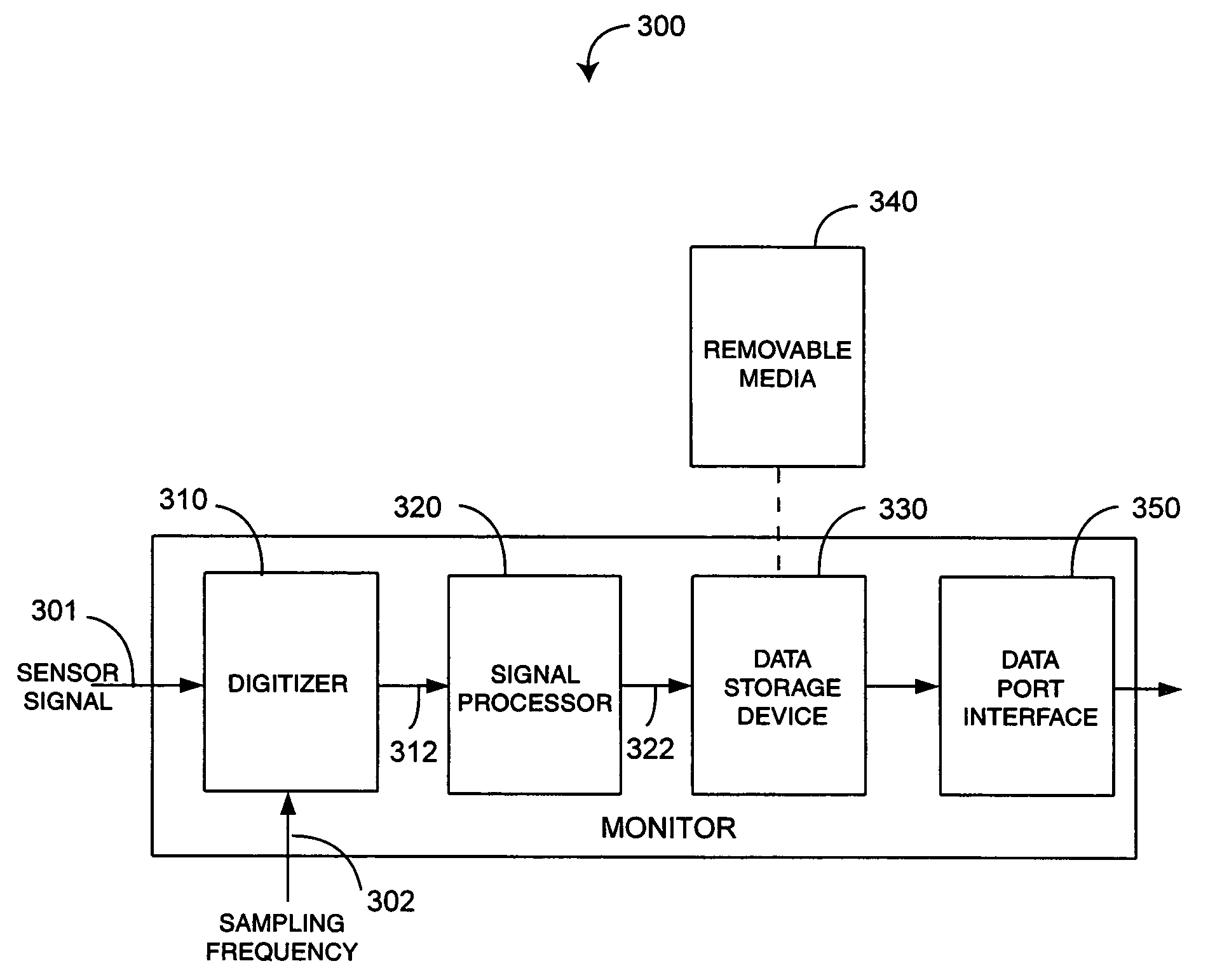
[0020]FIG. 4 illustrates a docking station embodiment 400 of a data capture system 300 (FIG. 3). A docking station 401 has a CPU 410, a data storage device 420 and an associated removable storage media 430. The docking station communicates with a portable pulse oximeter via input UART signals 402 and with an external device via output UART signals 403. The docking station CPU 410 communicates with the data storage device 420 using internal UART signals 412. The CPU 410 receives pulse oximetry and related data from the portable via the input UART signals 402 and may generate additional data in response. The received portable data and / or the CPU generated data is transmitted to the data storage device 420 via the internal UART signals 412 and recorded on the removable media 430 accordingly, as described in further detail below.

embodiment 500

[0021]FIGS. 5A-E illustrate a particular docking station embodiment 500 of a pulse oximetry data capture system 400 (FIG. 4). The data storage device 520 (FIG. 5E) is a Flashcore-B available from TERN, Inc., Davis, Calif., and the removable storage media 530 (FIG. 5E) is a 256 MB Compact Flash card. The data storage device 520 is installed internally to the docking station 510 adjacent a circuit board 540 (FIG. 5E) and proximate the docking station bottom 501. The docking station 510 supplies power to the data storage device 520. The data storage device 520 transparently passes-through the internal UART signals 412 (FIG. 4) to the output UART signals 403 (FIG. 4). A slot 550 is created in the bottom of the docking station 510, which allows insertion and removal of the storage media 530 into and out of the storage device 520. One of ordinary skill will recognize that the data storage device 520 and associated removable media 530 can utilize various data storage technologies other tha...


PUM


Abstract

A data capture system utilizes a sensor with emitters adapted to transmit light into a fleshy medium and a detector adapted to generate intensity signals in response to receiving light after absorption by the fleshy medium. A monitor is configured to input the intensity signals, generate digitized signals from the intensity signals at a sampling rate and compute at least one physiological parameter responsive to magnitudes of the digitized signals. A data storage device is integrated with the monitor and is adapted to record data derived from the digitized signals on a removable storage media at the sampling rate.

Description

CROSS-REFERENCE TO RELATED APPLICATIONS[0001]This application relates to and claims the benefit of prior U.S. Provisional Patent Application No. 60 / 518,051 entitled Pulse Oximetry Trend Data Storage System, filed Nov. 7, 2003 and incorporated by reference herein.BACKGROUND OF THE INVENTION[0002]Pulse oximeters have gained rapid acceptance in a wide variety of medical applications, including surgical wards, intensive care units, general wards and home care by providing early detection of decreases in the arterial oxygen supply, reducing the risk of accidental death and injury. FIG. 1 illustrates a pulse oximetry system 100 having a sensor 110 applied to a patient, a monitor 120, and a patient cable 130 connecting the sensor 110 and the monitor 120. The sensor 110 has emitters (not shown) and a detector (not shown) and is attached to a patient at a selected fleshy medium site, such as a fingertip 10 as shown or an ear lobe. The emitters are positioned to project light of at least two ...

Claims


Application Information

Patent Timeline
Patent Type & Authority Patents(United States)
IPC IPC(8): A61B5/1455A61B5/00
CPCA61B5/0002A61B5/14551A61B2560/0456A61B2560/0475
Inventor AL-ALI, AMMARMUHSIN, BILALLEE, MICHAEL
Owner JPMORGAN CHASE BANK NA
Why Eureka
Try Eureka