
Pulse width converged method to control voltage threshold (Vt) distribution of a memory cell

a voltage threshold and converged method technology, applied in static storage, digital storage, instruments, etc., can solve the problems of affecting the time it takes to erase a memory cell, many reliability issues, and degradation of the nitride trapping memory cells, so as to reduce the power requirements for implementing programming and achieve good charge/data retention, the effect of reducing the power requiremen

Inactive Publication Date: 2008-05-13
MACRONIX INT CO LTD
View PDF20 Cites 13 Cited by
  • Summary
  • Abstract
  • Description
  • Claims
  • Application Information

AI Technical Summary

Benefits of technology

This approach results in better charge / data retention, high scaling capabilities, and reduced complexity in programming and erasing operations, minimizing stress on memory cells and enhancing data reliability.

Problems solved by technology

A typical nitride trapping memory cell utilizes a relatively thick tunnel oxide layer, which typically negatively influences the time it takes to erase a memory cell.
However, BTBHHT erasing causes many reliability issues and degradation of the nitride trapping memory cells by increasing charge losses after many program / erase operation cycles.
U.S. Pat. No. 6,219,276 (Parker) and U.S. Pat. No. 6,320,786 (Chang et al.) disclose methods that requires the use of multiple programming voltages for achieving multiple voltage threshold (Vt) distributions, which increases the design complexity, wherein the programming voltages are not constant.
This method increases the design complexity for controlling program voltages since the voltages are not constant during the programming operation.
Furthermore, Haddad does not control the voltage threshold distribution of each memory cell by varying a pulse width of a programming pulse that is applied to each memory cell.
The prior art methods cited above, rely on more complex designs that are less efficient and more costly to implement, which impinge on the overall MLC operation and effectiveness of the non-volatile memory cell, regardless of whether one uses nitride trapping memory or PHINES cells.
Moreover, the prior art methods do not consider issues related to the over-programming and over-erasing of memory cells, wherein these issues have a detrimental effect on the memory cell's charge retention as well as the cell's life cycle.

Method used


Image

  • Pulse width converged method to control voltage threshold (Vt) distribution of a memory cell
  • Pulse width converged method to control voltage threshold (Vt) distribution of a memory cell
  • Pulse width converged method to control voltage threshold (Vt) distribution of a memory cell

Examples


Embodiment Construction

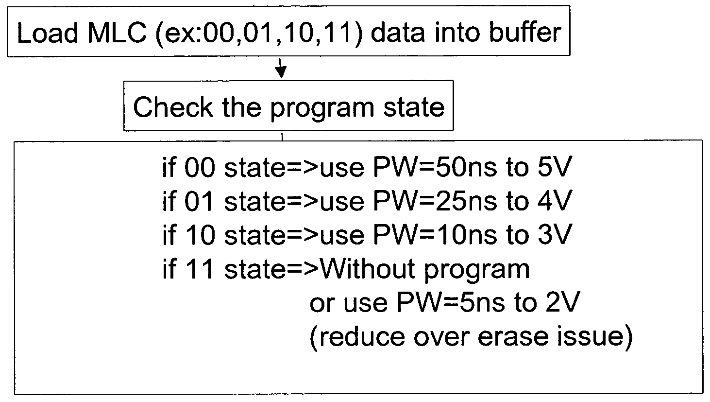
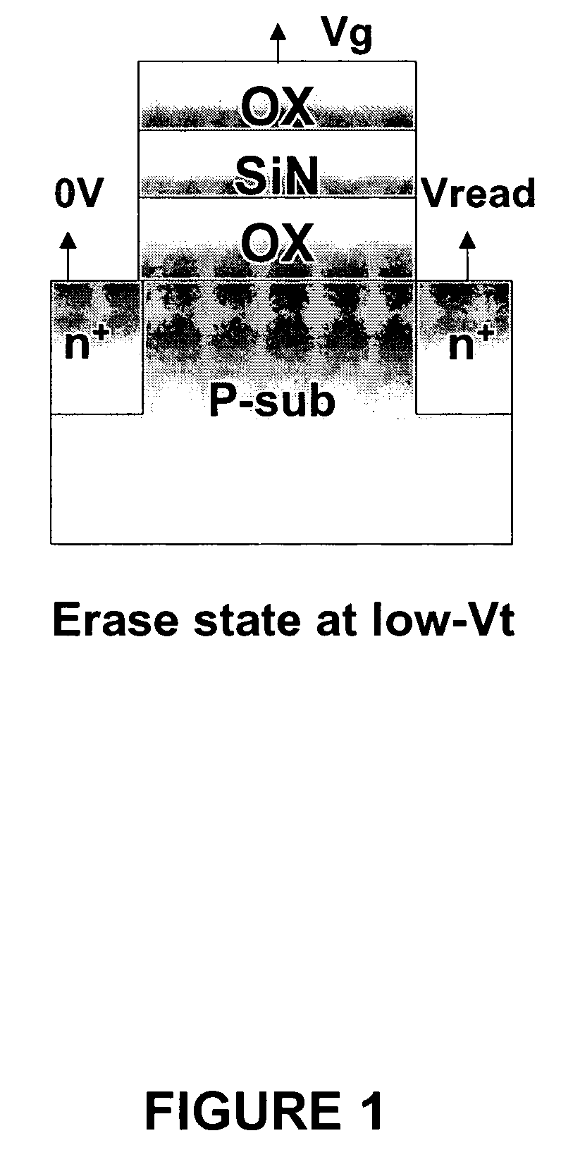
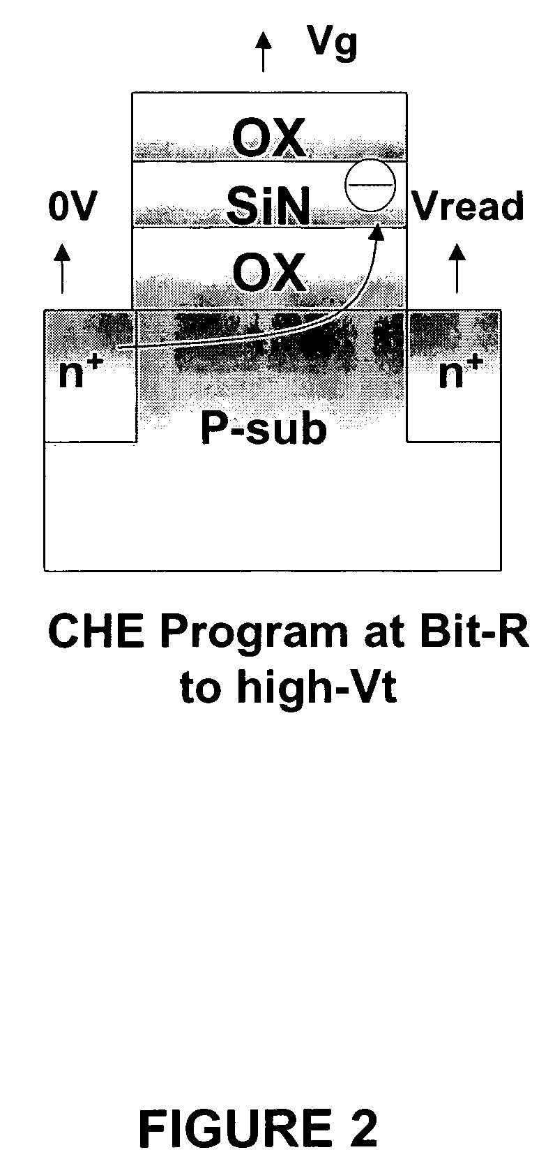
[0037]A pulse width converged method is used to control voltage threshold (Vt) distributions during the operation of a plurality of multi-level storage memory cells. Particularly, the method of the present invention is related to a plurality of nitride trapping memory cells and a plurality of PHINES cells, but other multi-level memory cells can be used with the present invention. Furthermore, the present invention relates to the operation on a plurality of non-volatile multi-level memory cells, wherein the operation includes programming and erasing, and the cells are capable of storing multiple independently charge bits (e.g., data bits) in a charge storage layer.

[0038]The present invention controls the voltage threshold (Vt) distributions during the operation of a plurality non-volatile memory cells by varying the pulse width while maintaining constant operating voltages. The operation of the non-volatile multi-level memory cells is either a programming operation or an erasing oper...


PUM


Abstract

A method of operating on a plurality of non-volatile multi-level memory cells is disclosed. The memory cells have at least a first, second, third and fourth program level. Each of program levels corresponds to a different binary state and has a voltage threshold distribution. A constant operating voltage is maintained on the memory cells and the voltage threshold distribution of the memory cell is controlled by varying a pulse width of a programming pulse applied to each memory cell.

Description

BACKGROUND OF THE INVENTION[0001]The present invention relates to a method of controlling the voltage threshold (Vt) distribution utilizing a pulse width during the operation of a plurality of non-volatile multi-level memory cells, and more particularly, to non-volatile multi-level memory cells having a two-bit per cell storage layer. The method is applicable to the operations of programming and erasing non-volatile multi-level memory cells, such as, but not limited to, nitride trapping memory and PHINES cells.[0002]Non-volatile multi-level memory refers to types of semiconductor memories that maintain stored information when a power source is not applied to the memory. Some examples of non-volatile memory cells include Mask Read-Only Memory (Mask ROM), Programmable Read-Only Memory (PROM), Erasable Programmable Read-Only Memory (EPROM) and Electrically Erasable Programmable Read-Only Memory (EEPROM). Typically, non-volatile memory cell data can be programmed, read and / or erased, an...

Claims


Application Information

Patent Timeline
Patent Type & Authority Patents(United States)
IPC IPC(8): G11C16/04
CPCG11C16/0466
Inventor WU, CHAO I
Owner MACRONIX INT CO LTD
Learn More