Monolithic, spatially-separated, common path interferometer

a common path, monolithic technology, applied in the field of interferometry, can solve the problems of limiting the measurement resolution to approximately 1 nanometer, complex devices that are cumbersome to deploy and align, and various mechanical, thermal, optical variations, so as to improve the resolution over polarization-separated interferometers, reduce errors, and simplify deployment and maintenance of those systems

Active Publication Date: 2008-05-13
LOCKHEED MARTIN CORP
View PDF7 Cites 4 Cited by
  • Summary
  • Abstract
  • Description
  • Claims
  • Application Information

AI Technical Summary

Benefits of technology

[0008]The present invention addresses the problems noted above by providing a monolithic, spatially-separated, common-path interferometer. The optical components of the interferometer are bonded together, which allows the interferometer to be permanently aligned at the time of assembly. This further allows systems using the interferometer to be small, compact and light weight and simplifies deployment and maintenance of those systems. To reduce errors and improve resolution over polarization-separated interferometers, the interferometer of the invention is designed to use spatially separated signal measurement and reference beams. One example of this spatially-separated architecture uses the core of a signal beam as the signal measurement beam and the annulus of the signal beam as the signal reference beam. Finally, the interferometer is designed so that the signal measurement and reference beams travel on a common path through the optical components of the interferometer. In this manner, the effect of relative mechanical, thermal, and optical variations within the interferometer are minimized, resulting in a more accurate and stable interferometry system.

Problems solved by technology

Subsequently, when the polarization separated beams are mixed together, the beams interfere with each other, creating an interference pattern or an interferogram.
Polarization-separated interferometers, however, suffer from polarization leakage, which can introduce errors and limit the measurement resolution to approximately 1 nanometer.
Existing interferometers are also large, complex devices that are cumbersome to deploy and difficult to align.
In addition, they suffer from various mechanical, thermal, and optical variations within the many components that make up the interferometers.

Method used


Image

  • Monolithic, spatially-separated, common path interferometer
  • Monolithic, spatially-separated, common path interferometer
  • Monolithic, spatially-separated, common path interferometer

Examples


Embodiment Construction

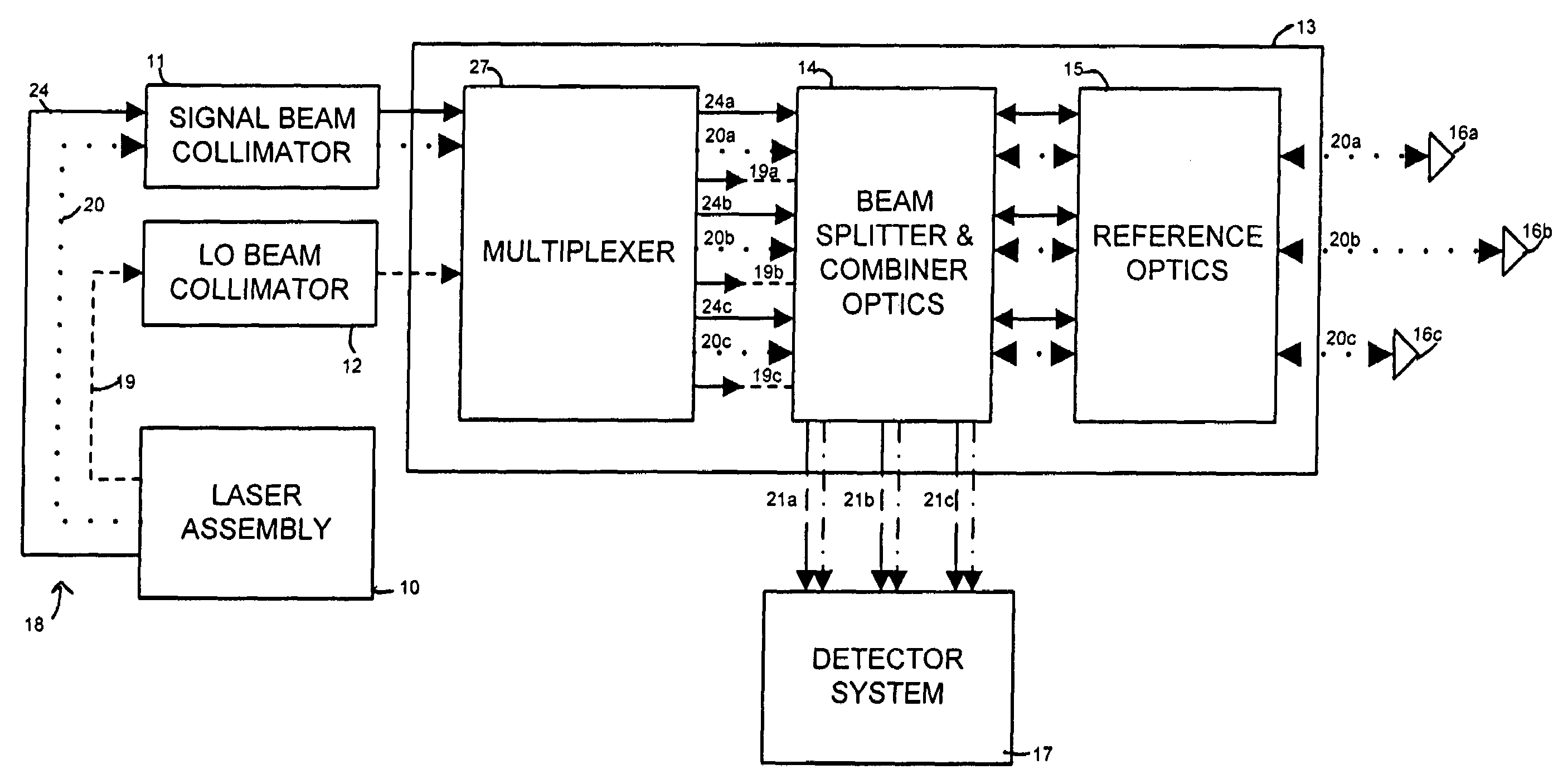
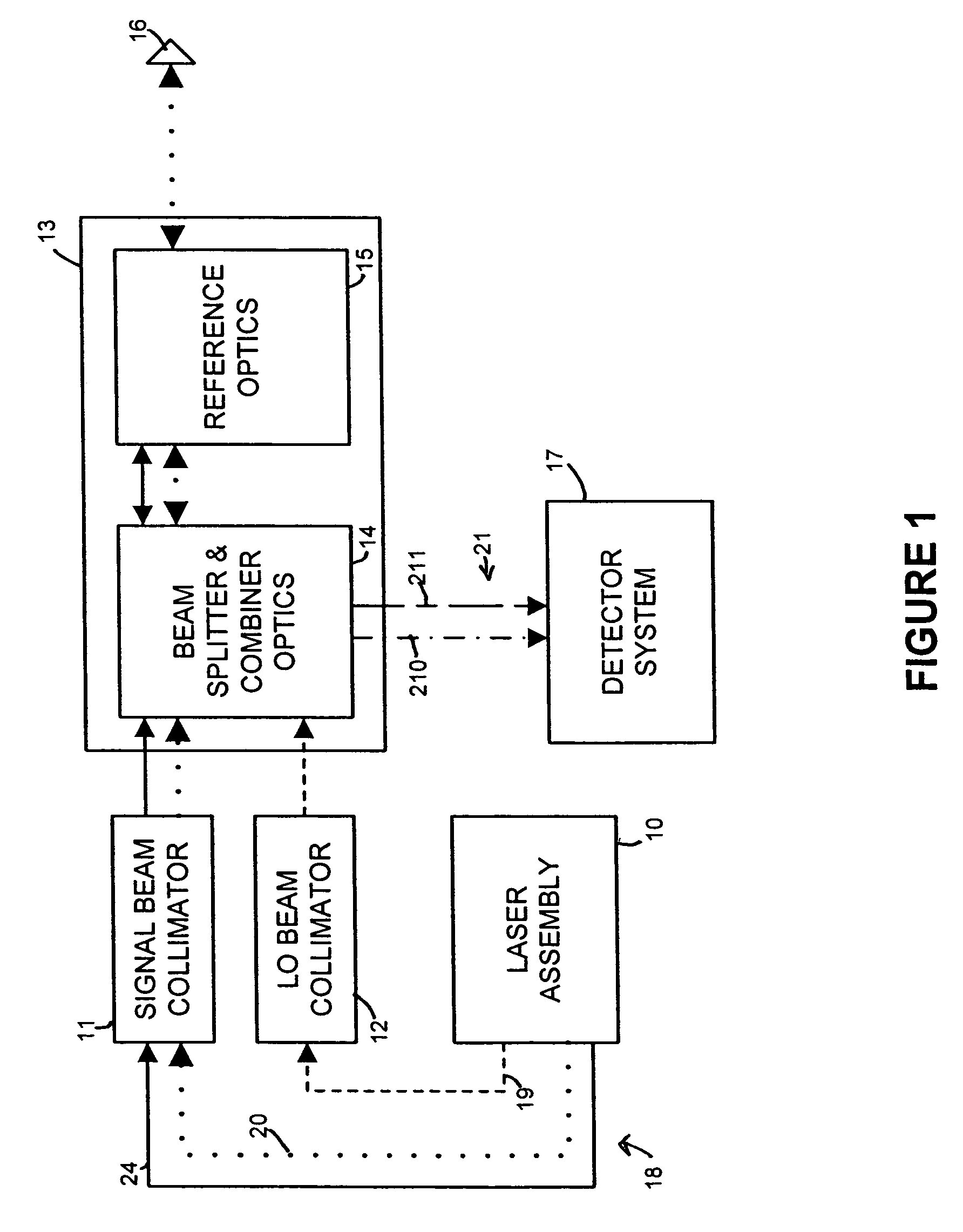
[0019]FIG. 1 is a block diagram depicting the primary components of a metrology gauge utilizing a monolithic, spatially-separated, common-path interferometer according to one embodiment of the invention. As shown in FIG. 1, the metrology gauge includes laser assembly 10, signal beam collimator 11, local oscillator (LO) beam collimator 12, interferometer 13, which is comprised of beam splitter and combiner optics 14 and reference optics 15, measurement reflector 16 and detector system 17.

[0020]Laser assembly 10 provides a signal beam 18, which includes signal measurement beam 20 (depicted as a dotted line) and signal reference beam 24 (depicted as a solid line), and LO beam 19, which is depicted as a dashed line, to signal beam collimator 11 and LO beam collimator 12, respectively. Signal measurement beam 20 and signal reference beam 24 are spatially distinct beams, as described in more detail below. The beams are generated within laser assembly 10 using one or more laser sources tog...


PUM


Abstract

Spatially-separated heterodyne interferometer architecture is combined with monolithic glass construction techniques to provide a monolithic, spatially-separated, common-path interferometer. The monolithic interferometer includes multiple optical components bonded together into a monolithic structure. The bonded components provide both optics and structure for the interferometer, thereby producing a small, compact, and light-weight interferometry system. Beam splitters and combiners are provided on the interfaces between the optical components to direct and combine signal measurement, signal reference and local oscillator beams used in the interferometry system. The spatially-separated architecture reduces cyclic error values below those of polarization-separated interferometers. In addition, the monolithic architecture of the interferometer minimizes the impact of mechanical, thermal, and optical variations within the system.

Description

STATEMENT AS TO RIGHTS TO INVENTIONS MADE UNDER FEDERALLY SPONSORED RESEARCH OR DEVELOPMENT[0001]The U.S. Government has a paid-up license in this invention and the right in limited circumstances to require the patent owner to license others on reasonable terms as provided for by the terms of [CONTRACT NO.] awarded by [AGENCY].BACKGROUND OF THE INVENTION[0002]1. Field of the Invention[0003]The present invention relates generally to interferometry, and specifically to a monolithic, spatially-separated, common-path interferometer.[0004]2. Description of the Related Art[0005]Interferometry has applications in many fields where precise measurement of movement is necessary. Fields using interferometry include aerospace, semiconductors, and general metrology.[0006]Traditionally, interferometers utilize polarizing beam splitters to separate a measurement beam from a reference beam. The measurement beam is then reflected off a measuring object and the reference beam off a fixed reference ob...

Claims


Application Information

Patent Timeline
Patent Type & Authority Patents(United States)
IPC IPC(8): G01B9/02
CPCG01B9/02051G01B9/02003G01B9/02027G01B9/02057G01B2290/70
Inventor SULLIVAN, MARK T.DRIES, LAWRENCE J.LEARY, DAVID F.
Owner LOCKHEED MARTIN CORP
Why Eureka
Try Eureka