
Mobile hard disk drive free fall detection and protection

a mobile hard disk drive and free fall detection technology, applied in the field of disk drives, can solve the problems of system believing a fall is occurring, actual free fall event not being detected, system not being able to detect free fall by monitoring the change of acceleration alone, etc., to achieve reliable, faster and more precise ways of measuring free fall

Active Publication Date: 2008-05-06
SEAGATE TECH LLC +1
View PDF19 Cites 76 Cited by
  • Summary
  • Abstract
  • Description
  • Claims
  • Application Information

AI Technical Summary

Benefits of technology

[0014]It is an aspect of the present invention to provide a more reliable, quicker and more precise way to measure free fall. One embodiment of the present invention monitors both the accelerometer output and the spindle speed change to detect free fall and / or tumble events. Another embodiment of the present invention employs a free fall detection algorithm that compares acceleration and the change of acceleration to respective threshold levels to detect a free fall event. These embodiments will detect free falls under different conditions and over shorter distances and thereby protect the disk drive in a wider variety of circumstances. One or more embodiments of the present invention can timely detect falls and complete responsive action to secure the actuator arm within a fall distance of approximately four inches.
[0016]In another embodiment of the present invention, the accelerometer is interconnected to the printed circuit board or a substrate of the disk drive rather than a structure outside of the disk drive, such as the mother board of a laptop computer. When acceleration is detected, critical time is not lost by transmitting the command through an interface between the computer and the disk drive. This allows detection and protection against falls from lower elevations. Further, if the sensor is placed on the computer mother board or at some location outside of the disk drive regardless if the application is in a computer or some other electronic device, the signal to secure the actuator arm or park the head may not be able to be received by the voice coil motor of the disk drive, for example, if the computer is locked up. For this reason, connecting the accelerometer inside the disk drive increases reliability.
[0019]It is yet another aspect of the present invention to reduce the effects of spindle jitter that may incorrectly cause a tumble detection system to determine a tumble event is occurring. Spindle “jitter” includes bearing load variations, non-constant loading, seeks, electronic noise, magnetic couplings, etc. Since jitter produces an instantaneous change between expected velocity and measured velocity of the disk spindle, jitter may cause the system to believe it is tumbling. Jitter is typically a problem when spin rates are assessed using analog or hardware controls. As a result, when jitter is present, the threshold that is used to indicate disk drive is tumbling is typically increased to avoid false triggers. Increasing the threshold increases the readings that are required to ensure that the data being collected are not the result of jitter, but are indicative of a tumble condition. Thus, the performance of the system is affected since the detectable drop height of the disk drive must be increased to account for the increased threshold related to filtering out the effects of jitter. To address the problems of jitter caused by analog-based hardware control, one embodiment of the present invention measures spin rate based upon the timing of zero-crossings in the stator induced by back EMF. Rather than monitoring the timing between successive zero crossings, the system assesses an average spin rate over a number of zero crossings. The average spin rate or spindle speed is then compared to a predicted or expected value over a predetermined time interval. By tracking the average disk spin velocity or spin rate with a low pass filter, the offset can be removed from the calculation. If the average spin rate exceeds a threshold value for a predetermined time period, the system determines a tumble event is occurring and corrective action is taken. The threshold value is adjusted, usually increased, to account for the presence of jitter, which is treated as a fixed value. More specifically, the root mean square (RMS) value of spin rate error is calculated and this value is used to adjust the threshold level. As a result, the effects of jitter are accounted for.
[0021]It is yet another aspect of the present invention to provide a disk drive free fall and tumble detection system that may be customized. More specifically, it is contemplated that embodiments of the present invention have the ability to be selectively altered wherein the threshold levels of free fall and / or tumble may be increased, decreased or deactivated and / or the timing windows utilized in association with the threshold levels may be increased or decreased. This aspect has advantages, for example, when the system that embodies the disk drive is used on a train, bus, airplane, etc., where inherent vibrations may falsely indicate a tumbling or free fall condition that would park the head unnecessarily. In other words, the end user may select the desired sensitivity of the detection system.

Problems solved by technology

More specifically, the duration of simple vibrations experienced during jogging, dancing, or traveling on a train, bus or car that are below the threshold may cause the system to believe a fall is occurring.
On the other hand, reducing the threshold to make a detection system non-sensitive may result in actual free fall event not being detected when the offset of the accelerometer is large.
However, the system can not detect free fall by monitoring the change of acceleration alone since the change of acceleration is also close to zero when the disk drive is not falling.
Further, if the sensor is placed on the computer mother board or at some location outside of the disk drive regardless if the application is in a computer or some other electronic device, the signal to secure the actuator arm or park the head may not be able to be received by the voice coil motor of the disk drive, for example, if the computer is locked up.
In some instances, monitoring acceleration and change in acceleration alone may be insufficient.
If the rotational speed is high enough, the measured acceleration may be above the threshold or may be below the detection threshold for an insufficient amount of time.

Method used


Image

  • Mobile hard disk drive free fall detection and protection
  • Mobile hard disk drive free fall detection and protection
  • Mobile hard disk drive free fall detection and protection

Examples


Embodiment Construction

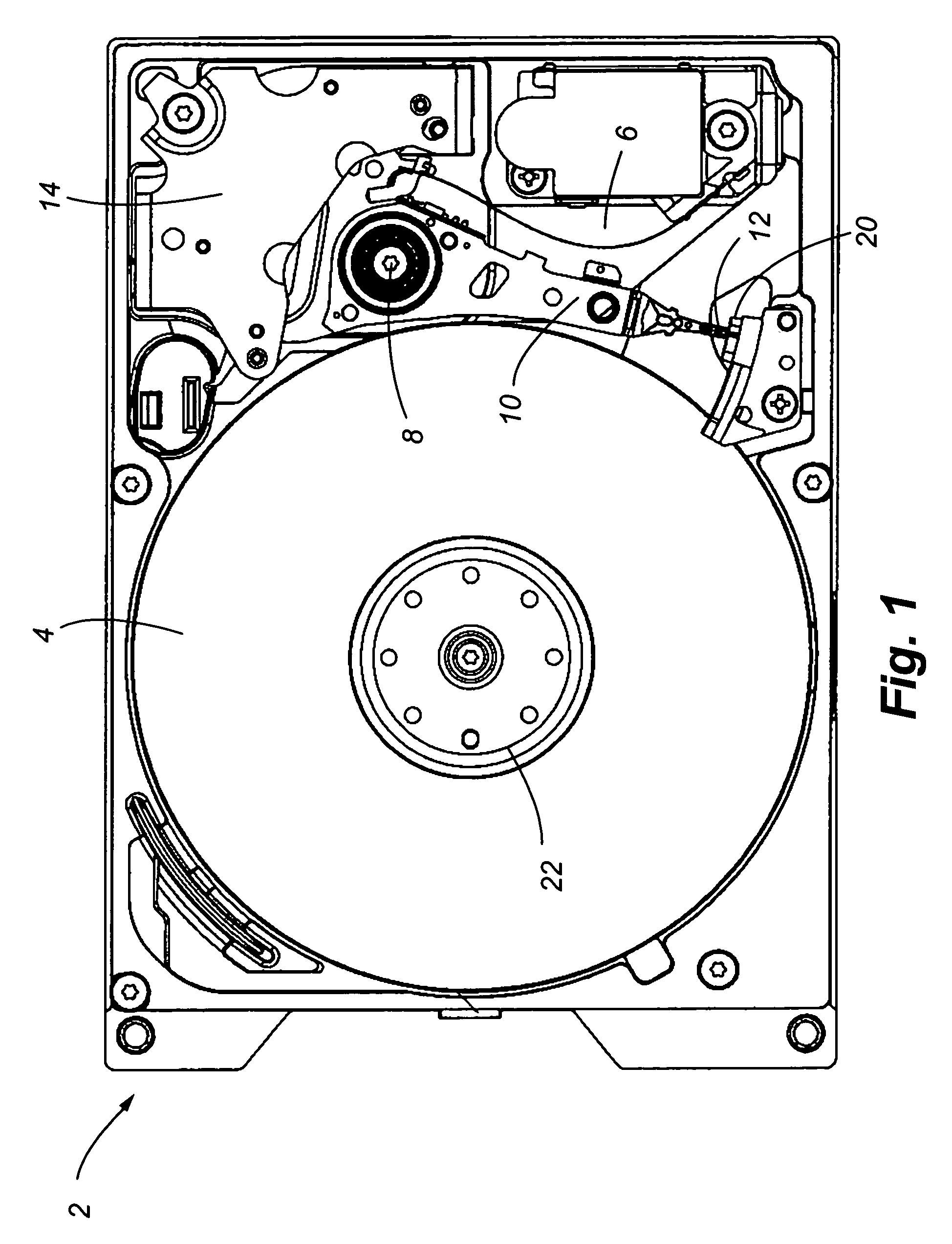
[0036]Referring now to FIG. 1, a partial perspective view of a common disk drive 2 is shown. Hard disk drives 2 employ one or more rotating disks 4 and an actuator assembly 6. The actuator assembly 6 rotates about a pivot 8 to radially position one or more actuator arms 10 relative to the surface of one or more disks 4. A read and / or write element or transducer 12 is positioned at the distal end of each actuator arm. A voice coil motor 14 selectively positions the head and / or write elements over a predetermined portion of a corresponding disk 4 for reading data from or writing data to the disk.

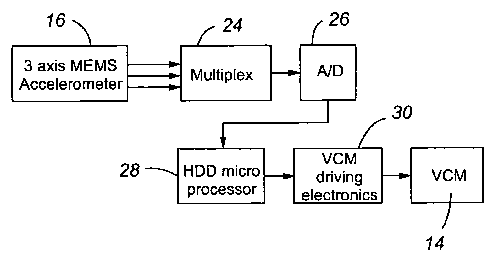
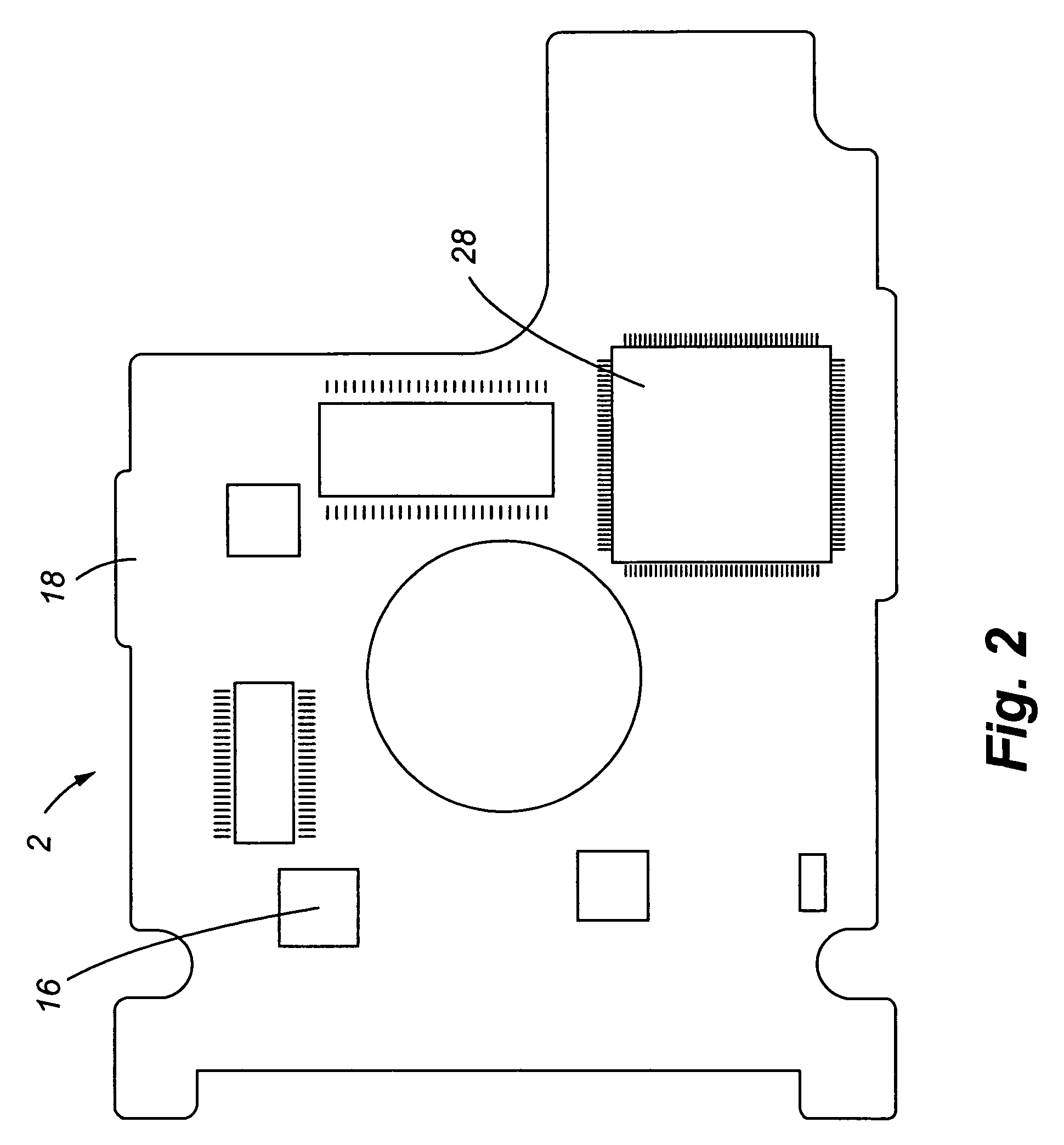
[0037]One embodiment of the present invention, shown in FIG. 2, further includes an accelerometer 16, preferably a three-axis accelerometer, interconnected to a printed circuit board 18 of the hard disk drive 2 to detect free fall acceleration of the disk drive. Certain implementations of this embodiment monitor acceleration and the change of acceleration over time to detect a free fall condit...


PUM


Abstract

A system provided for protecting a disk drive from impact damages. More specifically, a disk drive is provided that includes an accelerometer interconnected to a printed circuit board that detects free fall of the disk drive. In addition, the velocity of spinning disks of the disk drive is also monitored to assess changes in velocity thereof that may indicate the presence of a tumbling condition. Furthermore, the change in acceleration measured by the accelerometer is monitored to prevent false indications of free fall due to common vibrations. Thus an enhanced system is provided that protects disk drives from the effect of free falls under a wide variety of conditions and allowing for drops from shorter distances to be identified.

Description

[0001]This application claims the benefit of U.S. Provisional Patent Application Ser. No. 60 / 633,052 and No. 60 / 632,915 filed Dec. 3, 2004, both of which are incorporated by reference in their entireties herein. This application is also related to U.S. patent application entitled “ZERO-G OFFSET IDENTIFICATION OF AN ACCELEROMETER EMPLOYED IN A HARD DISK DRIVE,” filed Dec. 2, 2005, which is incorporated by reference in its entirety herein.FIELD OF THE INVENTION[0002]The present invention relates generally to disk drives, and more particularly, a method and apparatus for protecting rotating media and read / write heads of the disk drive from mechanical shock events caused by an impact following a fall. More specifically, the present invention repositions the actuator arm off the disk or over a crash zone when free fall and / or tumbling motion is detected.BACKGROUND OF THE INVENTION[0003]Conventional disk drives employ a servo system that controls the radial position of an actuator arm rel...

Claims


Application Information

Patent Timeline
IPC IPC(8): G11B5/54G11B21/12
CPCG11B5/5582
Inventor LI, YUNFENGSCHRECK, ERHARDGUO, WEIGLASSBURN, TIMHEIMBAUGH, MARKFLYNN, WILLIAMNORTHRUP, OLIVERSCURA, JOHN E.GUO, LINCHEW, XIAOKUN
Owner SEAGATE TECH LLC
Learn More