
Combined cycle power plant with auxiliary air-cooled condenser

a combined cycle and condenser technology, applied in mechanical equipment, machines/engines, lighting and heating equipment, etc., can solve the problems of reducing the efficiency of the combined cycle power plant, and increasing the difficulty of maintaining the exhaust pressure of the steam turbine below

Inactive Publication Date: 2008-05-06
SIEMENS ENERGY INC
View PDF18 Cites 7 Cited by
  • Summary
  • Abstract
  • Description
  • Claims
  • Application Information

AI Technical Summary

Benefits of technology

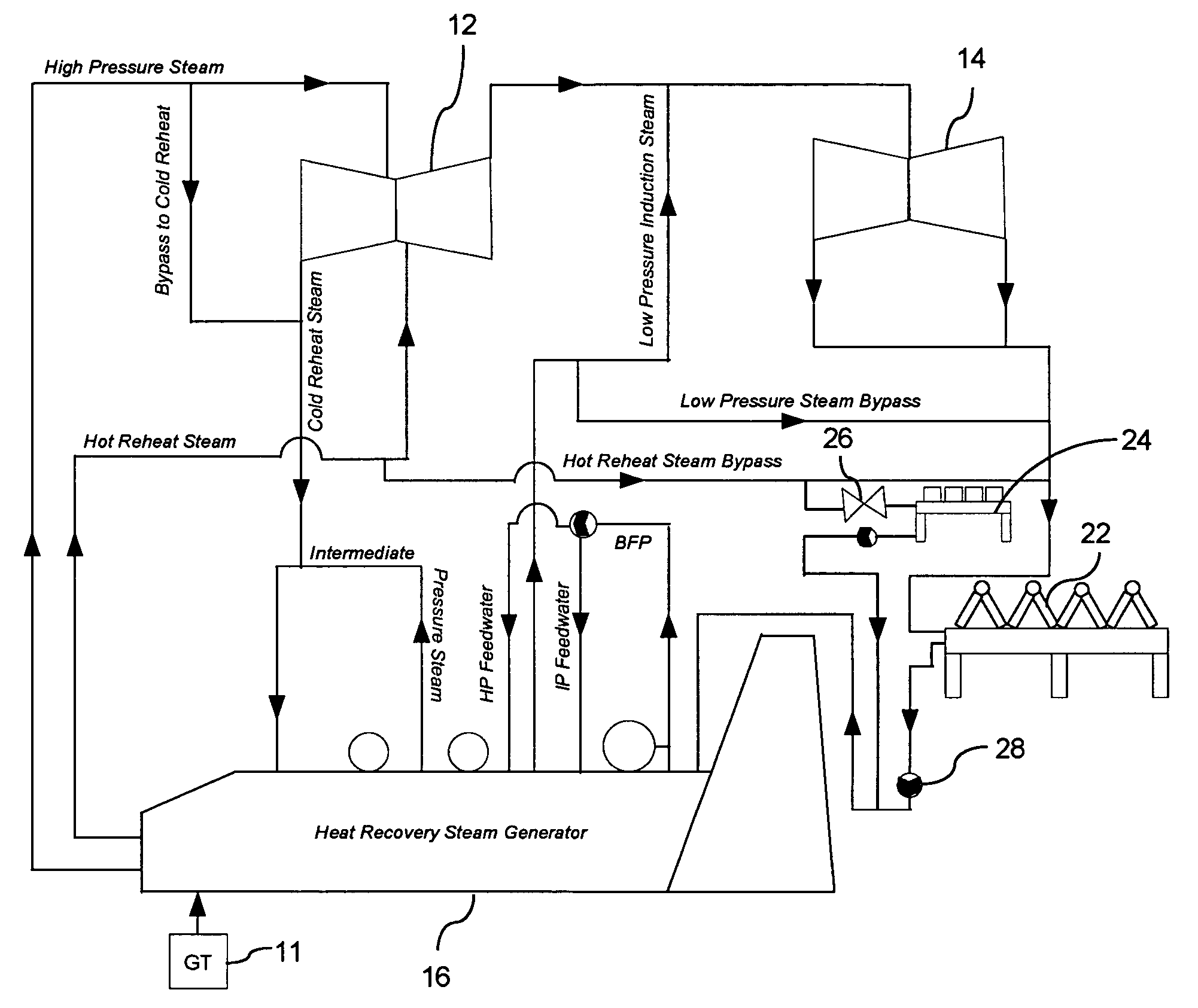
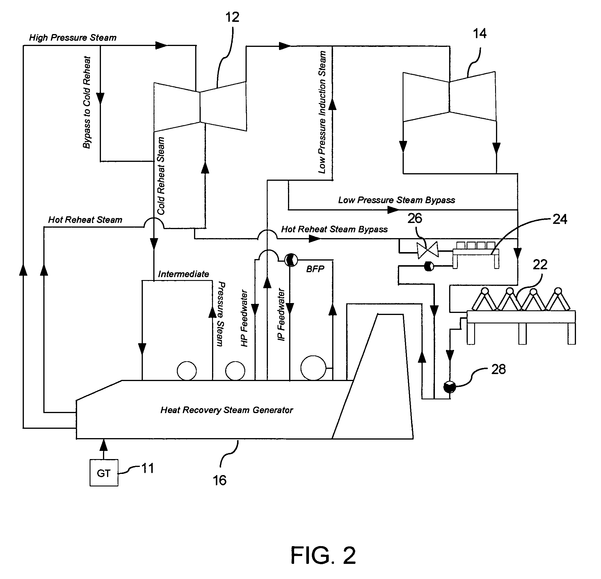
"The present invention provides an improved combined cycle power plant that can accommodate various operating criteria for plant startup or restart during a period of peak thermal load, such as a hot day, while reducing the cost of the overall power plant. This is achieved by supplementing the heat rejection capability of the main air-cooled condenser (ACC) with an auxiliary condenser that can be used during plant startup and steam bypass operation to reduce steam turbine back pressure. The auxiliary condenser is designed to operate at a higher pressure relative to the main ACC, which helps to further reduce the cost of the overall power plant."

Problems solved by technology

For air-cooled combined cycle power plants, such as may be deployed in relatively dry geographical regions where water is a scarce resource, one of the most severe sizing constraints for the ACC arises due to the requirement of being able to perform a plant startup or restart during a period of peak thermal load, such as on a hot day.
Hence, it is even more difficult on hot days to maintain the steam turbine exhaust pressure below the maximum allowable value for rolling the steam turbine.
This results in a need to quickly ramp the gas turbines to relatively high load levels prior to rolling the steam turbine, which makes maintaining low steam turbine back pressure prior to rolling the steam turbine very difficult.
In a practical implementation, such an approach would significantly increase the size and cost of the ACC without a corresponding improvement in base load plant performance and, as a result, the overall combined cycle power plant would be less cost effective.

Method used


Image

  • Combined cycle power plant with auxiliary air-cooled condenser
  • Combined cycle power plant with auxiliary air-cooled condenser
  • Combined cycle power plant with auxiliary air-cooled condenser

Examples


Embodiment Construction

[0012]The inventors of the present invention have recognized innovative and cost-effective techniques for providing an improved combined cycle pow of the present invention allow accommodating various operating criteria for plant startup or restart during a period of peak thermal load, such as during a hot day, while achieving a reduction in cost of the overall combined cycle power plant.

[0013]In one exemplary embodiment, the heat rejection capability of a main ACC 22 is supplemented by an auxiliary condenser 24, such as an air-cooled steam dump condenser that can be used during plant startup and steam bypass operation to supplement the heat rejection capability of the ACC 22, thereby reducing steam turbine back pressure.

[0014]In one exemplary embodiment, the auxiliary condenser 24 is selected to have different thermal characteristics relative to ACC 22. More particularly, auxiliary condenser 24 is configured to operate at a higher pressure (e.g., higher outlet pressure) relative to ...


PUM


Abstract

A combined cycle power plant (20) including a main air-cooled condenser (22) condensing steam at a first pressure and an auxiliary air-cooled condenser (24) condensing steam at a second pressure higher than the first pressure. Designing an air-cooled combined cycle power plant for startup on a hot day can significantly increase the size and cost of the required air-cooled condenser. Adding an auxiliary air-cooled condenser having appropriate thermal characteristics relative to a main air cooled compressor to the steam bypass circuit of an air-cooled combined cycle power plant enables the plant to meet plant startup requirements during periods of peak thermal load in a more cost effective manner than would be achievable with the main air cooled condenser alone.

Description

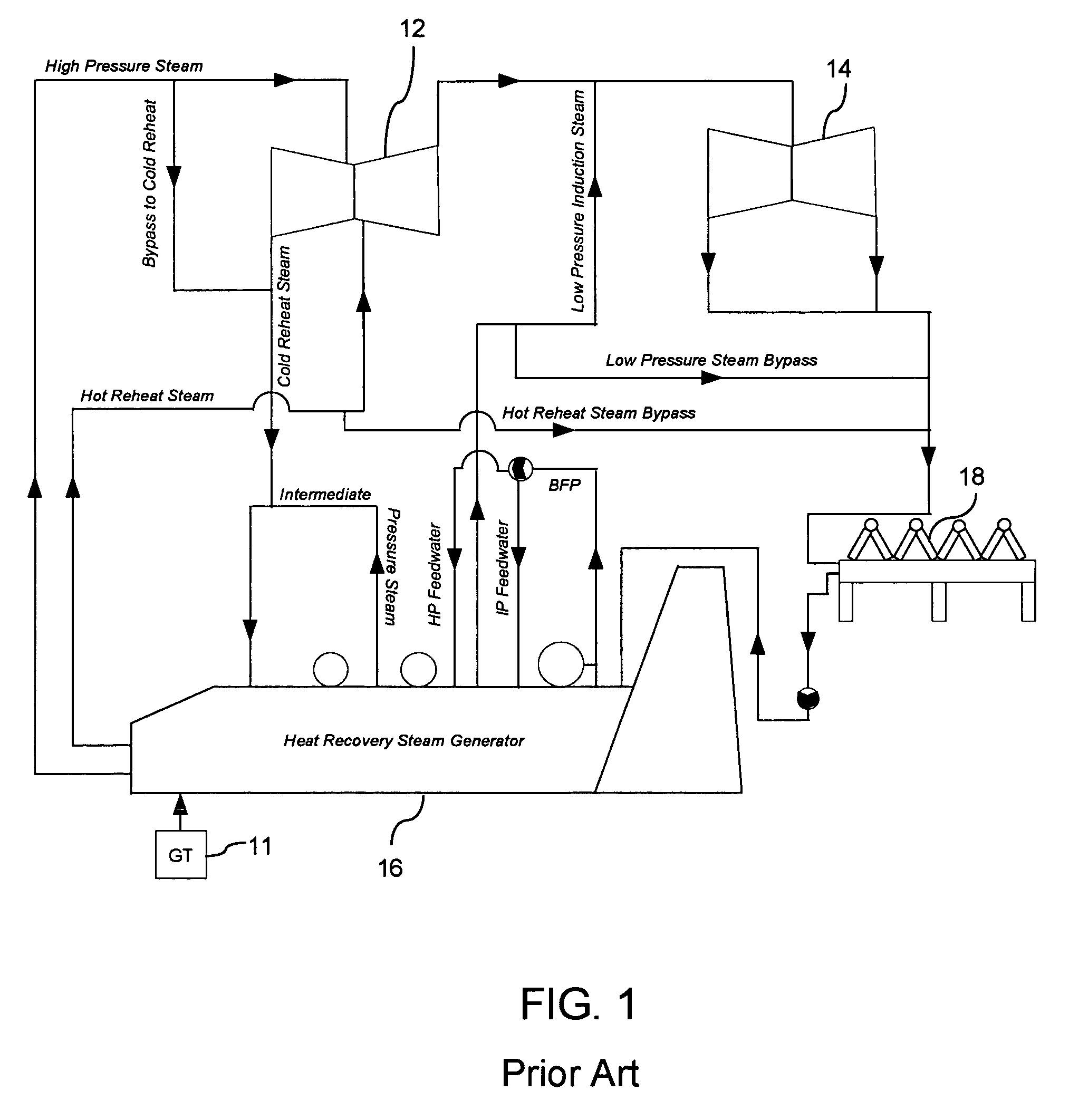
FIELD OF THE INVENTION[0001]The present invention is generally related to the field of power generation, such as a combined cycle power plant, and, more particularly, to air-cooled condensing apparatus for a combined cycle power plant.BACKGROUND OF THE INVENTION[0002]Combined cycle power plants are well known in the art. A combined cycle power plant includes both a gas turbine-based topping cycle and a steam turbine or a steam rankine bottoming cycle that is driven by heat in the exhaust of the gas turbine engine. U.S. Pat. No. 6,145,295, assigned in common to the assignee of the present invention, describes one exemplary combined cycle power plant.[0003]FIG. 1 is a simplified schematic of an exemplary combined cycle power plant 10 that may benefit from aspects of the present invention. Heat contained in an expanded working medium (e.g., flue gas) from at least one gas turbine (GT) 11 is utilized to generate steam for one or more steam turbines (e.g., steam turbines 12 and 14). The ...

Claims


Application Information

Patent Timeline
Patent Type & Authority Patents(United States)
IPC IPC(8): F02C6/00F02G1/00F02G3/00
CPCF01K9/00F01K23/10F28B1/06F28B7/00Y02E20/16
Inventor BRIESCH, MICHAEL S.
Owner SIEMENS ENERGY INC
Learn More