
Laminated armature core for an electric motor

a technology of armature core and electric motor, which is applied in the direction of windings, magnetic circuit rotating parts, magnetic circuit shape/form/construction, etc., can solve the problems of windings only being fixed in their position, forming bubbles, and not always absorbing impregnating material, etc., to ensure the protection of windings from mechanical wear from outside, and good introduction of winding wires

Inactive Publication Date: 2008-04-29
ROBERT BOSCH GMBH
View PDF15 Cites 9 Cited by
  • Summary
  • Abstract
  • Description
  • Claims
  • Application Information

AI Technical Summary

Benefits of technology

The invention is an armature packet for an electric motor that has improved stability and reduced vibration. It achieves this by using winding slots with different geometries that better fix the armature windings in their position. This reduces short-circuited coils and ensures the armature winding does not shift radially at high rpm. The influx conduits in the winding slots communicate with each other through a transverse conduit, which allows the impregnating material to reach all the winding wires very well. The armature laminations are produced using a stamping tool, which makes the production process simple and economical. The influx conduits have a constriction with undercuts to ensure good introduction of the winding wires and protection against mechanical wear. Overall, the invention provides a more stable and efficient armature packet for electric motors.

Problems solved by technology

However, in dip roller-burnishing and the drip process, the problem is that the impregnating material does not always penetrate all the voids between the armature windings.
Otherwise, uneven filling of the winding slots with impregnating material and air inclusions, which thus leads to the formation of bubbles.
As a result, the windings are fixed only inadequately in their position against the centrifugal forces that occur in operation and against vibration.
As a consequence, short-circuited coils occur along with vibration from radial shifting of the armature winding and hence of the center of mass, resulting in a shorter service life of the motor.
As a result, while the defects of impregnation are essentially compensated for, nevertheless this method is very complicated and thus expensive in the production process, and so it is employed only for high-quality motors.

Method used


Image

  • Laminated armature core for an electric motor
  • Laminated armature core for an electric motor
  • Laminated armature core for an electric motor

Examples


Embodiment Construction

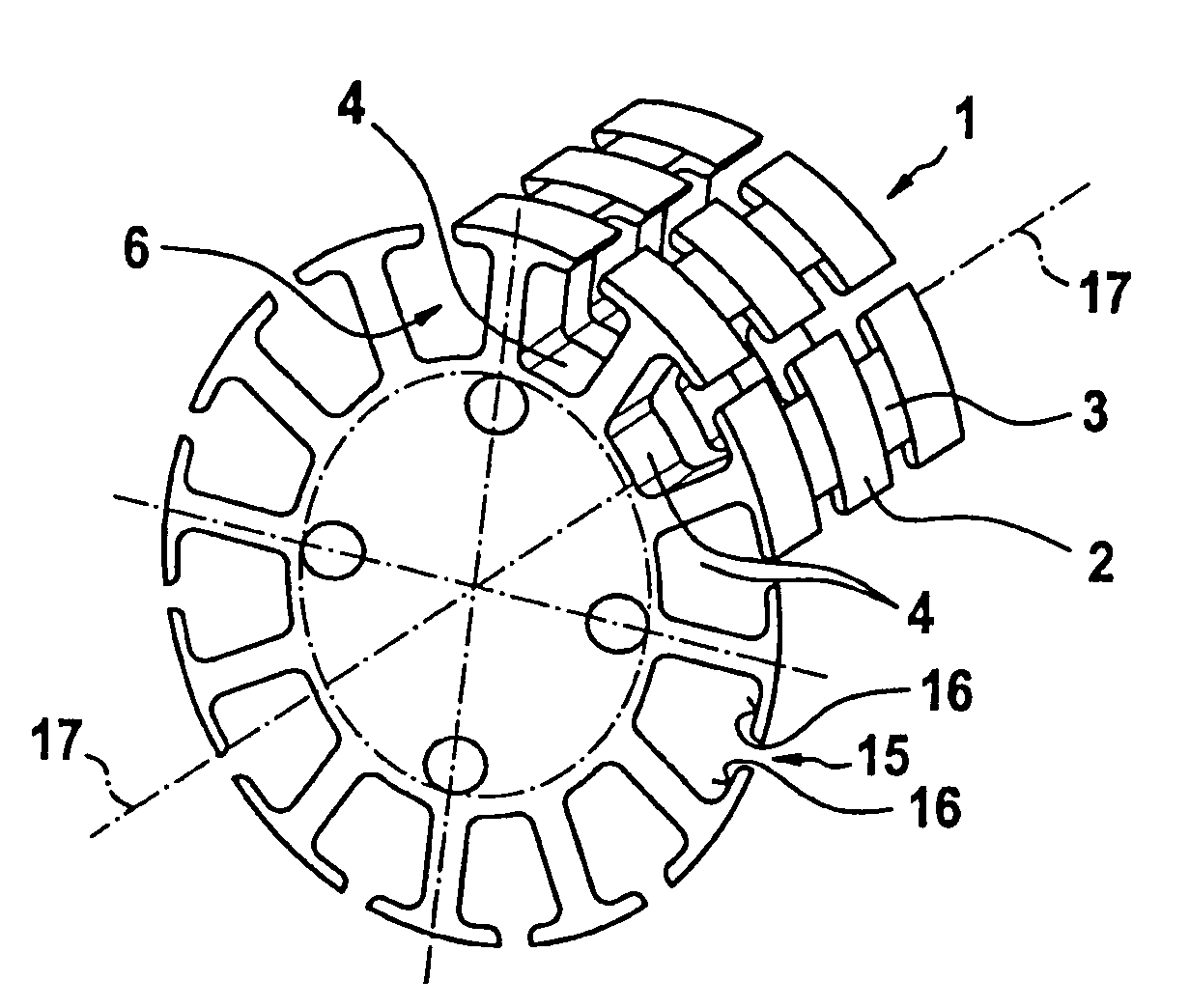
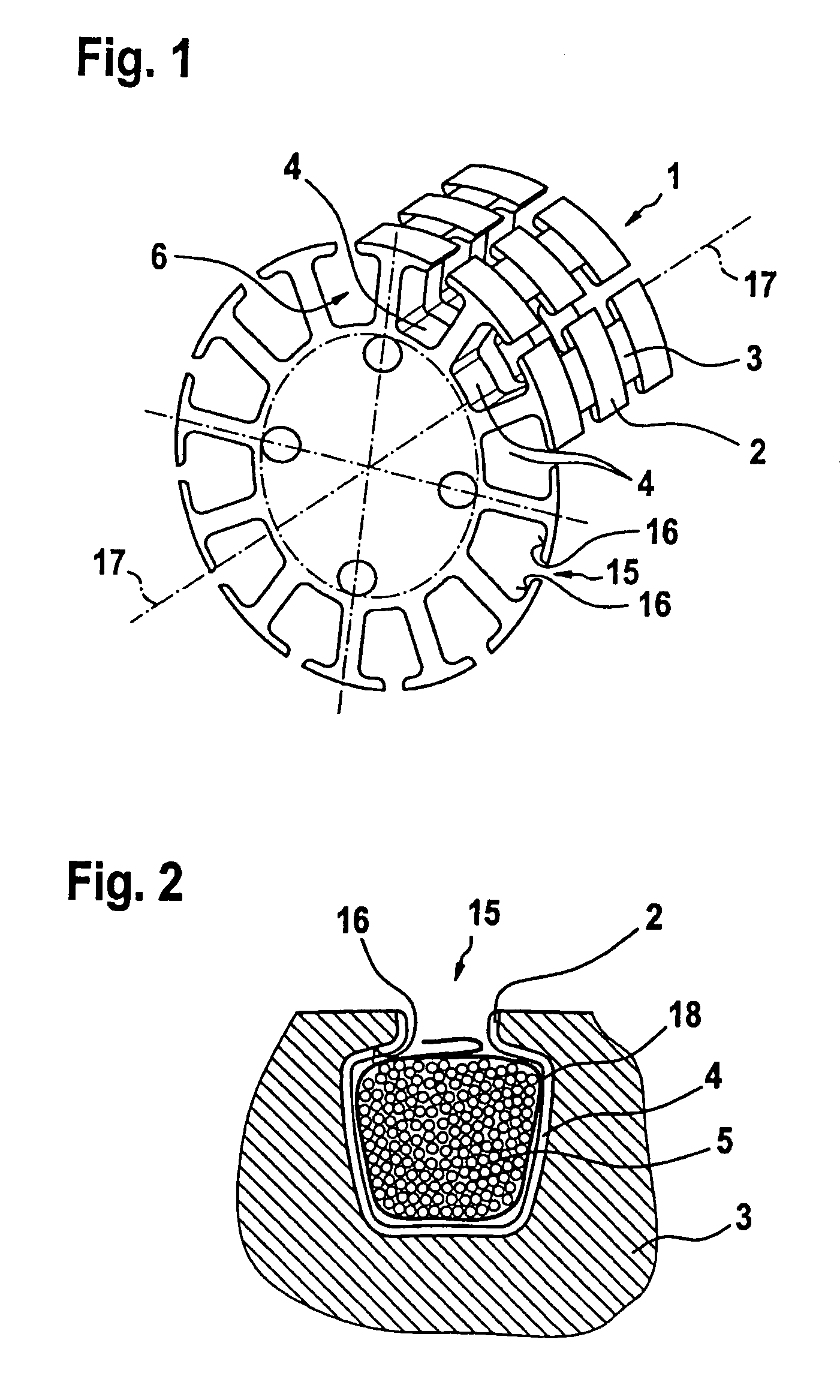
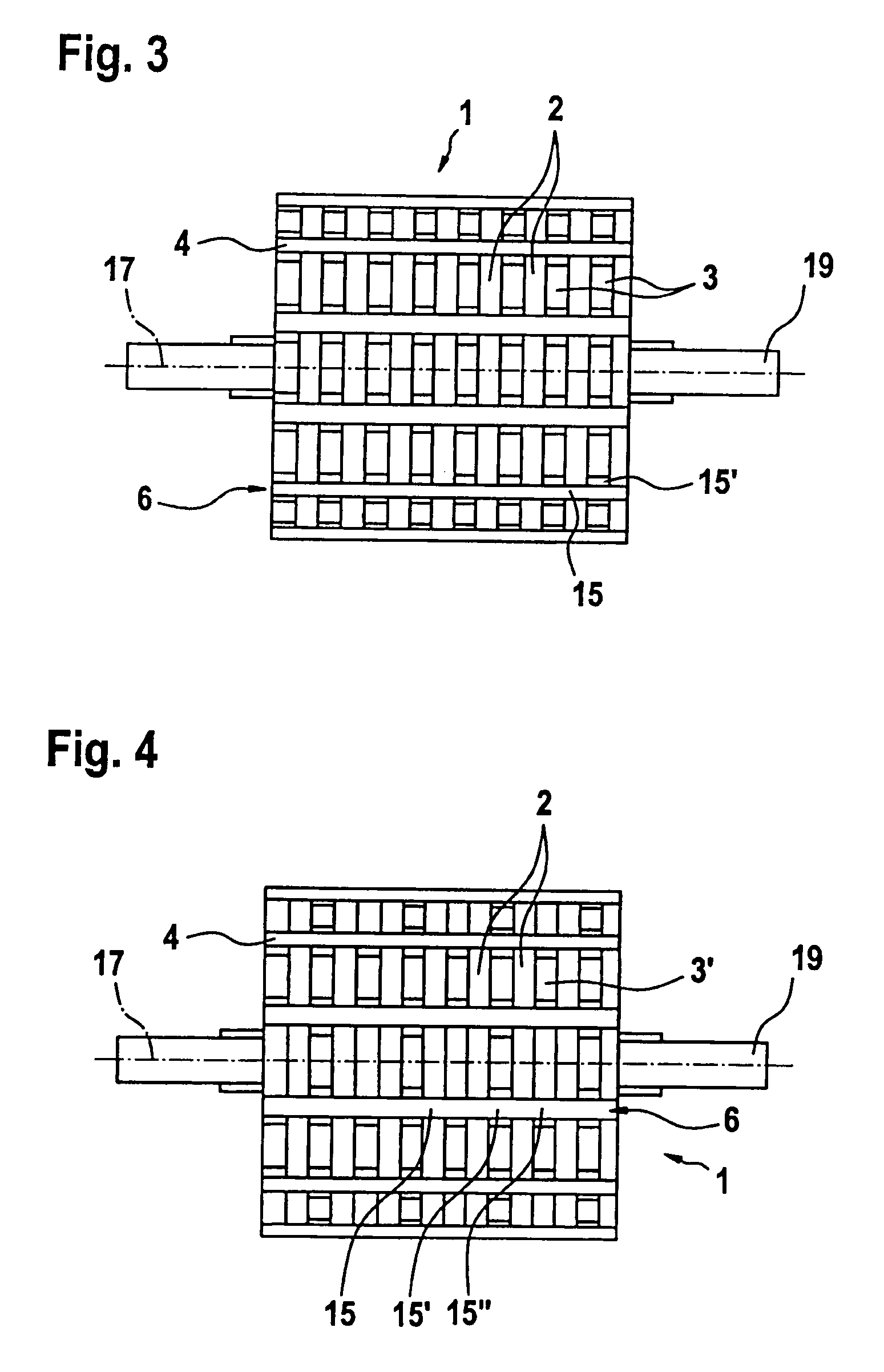
[0023]In FIGS. 1 through 3, a first exemplary embodiment of an armature packet 1 of the invention is shown. In FIG. 1, the armature packet 1 is shown without its armature winding 5 (see FIG. 2). The same is also true for FIG. 3. The armature packet 1 has a plurality of armature laminations 2, 3, lined up with one another along a central longitudinal axis 17. The armature laminations 2, 3 have winding slots 4 along their circumference. In the case shown, there are a total of twelve winding slots 4, which are each located equidistant from one another. The winding slots 4 are embodied such that on the circumference of the respective armature lamination 2, 3 they have a constriction 15, which widens via two undercuts 16 into a larger cross section. The twelve winding slots 4 are merely an example; any other number of winding slots 4 may also be embodied in the armature laminations 2, 3. The winding slots 4 need not be equidistant from one another, either.

[0024]The winding slots 4 of the...


PUM


Abstract

In an armature packet (1) for an electric motor, having a plurality of armature laminations (2, 3), in each of which a plurality of winding slots (4) for receiving an armature winding (5) are embodied, and the winding slots (4) of adjacent armature laminations (2, 3) are located in alignment with one another and form a conduit (6), a better positional fixation of the armature winding (5) is attained by providing that the winding slots (4), associated with one conduit (6), of different armature laminations (2, 3) have different geometries. The same is attained by providing that at least some of the winding slots (4) each have an influx conduit (11), each of which discharges into its region oriented toward the center of the armature packet (1).

Description

BACKGROUND OF THE INVENTION[0001]The invention is based on an armature packet for an electric motor.[0002]For producing armature packets for electric motors, individual armature laminations are stamped in such a way that recesses for armature windings are stamped into the lamination in the same operation. The armature windings are wound into these winding slots and fixed in their position by impregnation with a suitable material. In principle, there are two known methods for this.[0003]In dip roller-burnishing, the wound armature packet is sealed by being dipped and rolled in the impregnating material (such as polyester resin). Next, the impregnating material is hardened, so that the winding together with the armature packet forms a rigid structure. In the drip process, a variant of dip roller-burnishing, the armature packet is received, rotating, in a suitable device and the impregnating material is dripped onto it. Next, the impregnating material is hardened as in dip roller-burni...

Claims


Application Information

Patent Timeline
Patent Type & Authority Patents(United States)
IPC IPC(8): H02K1/00H02K1/16H02K1/26H02K1/32H02K15/12
CPCH02K1/165H02K1/265H02K1/32H02K15/12H02K3/48H02K15/024
Inventor WIKER, JUERGENSCHADOW, JOACHIMFRANK, MARIO
Owner ROBERT BOSCH GMBH
Learn More