
Fixing structure of circuit board and display module comprising the same

a technology of circuit board and display module, which is applied in the direction of electrical apparatus construction details, connection contact material, coupling device connections, etc., can solve the problems of increasing manufacturing costs and increasing processing time, and achieve efficient alignment and securing holes, efficient alignment and securing

Inactive Publication Date: 2008-04-29
SAMSUNG SDI CO LTD
View PDF15 Cites 44 Cited by
  • Summary
  • Abstract
  • Description
  • Claims
  • Application Information

AI Technical Summary

Benefits of technology

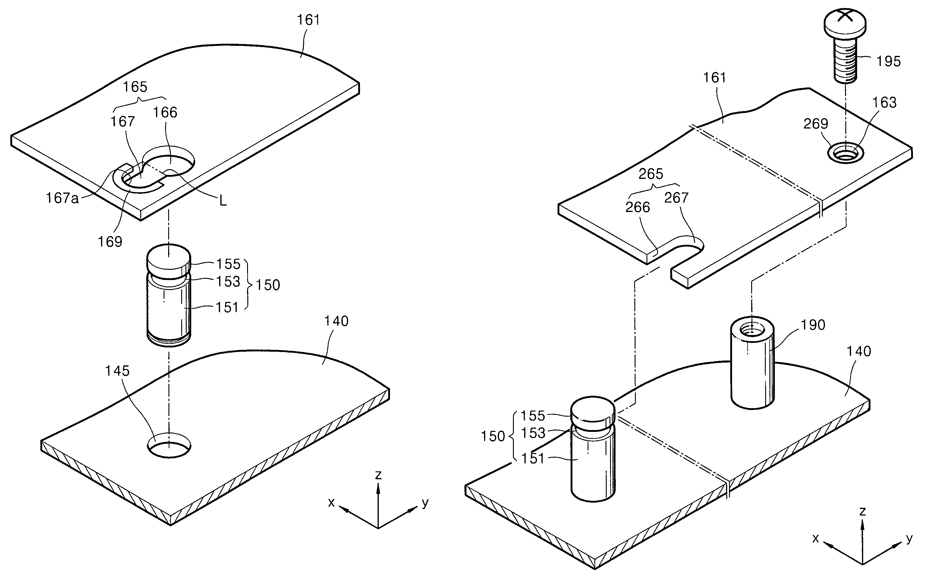
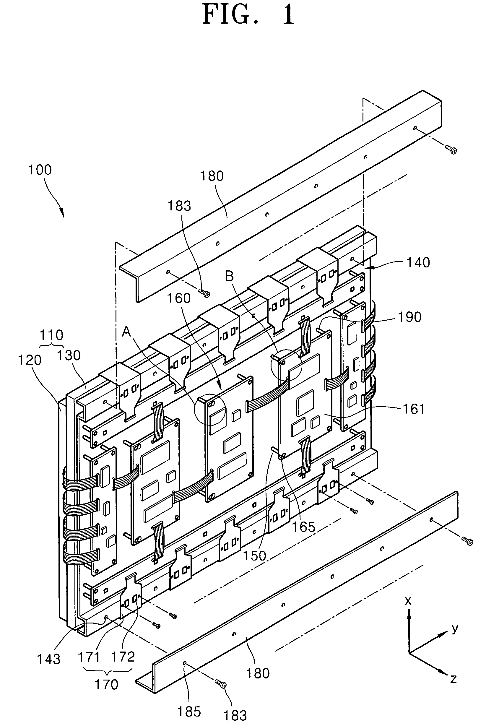
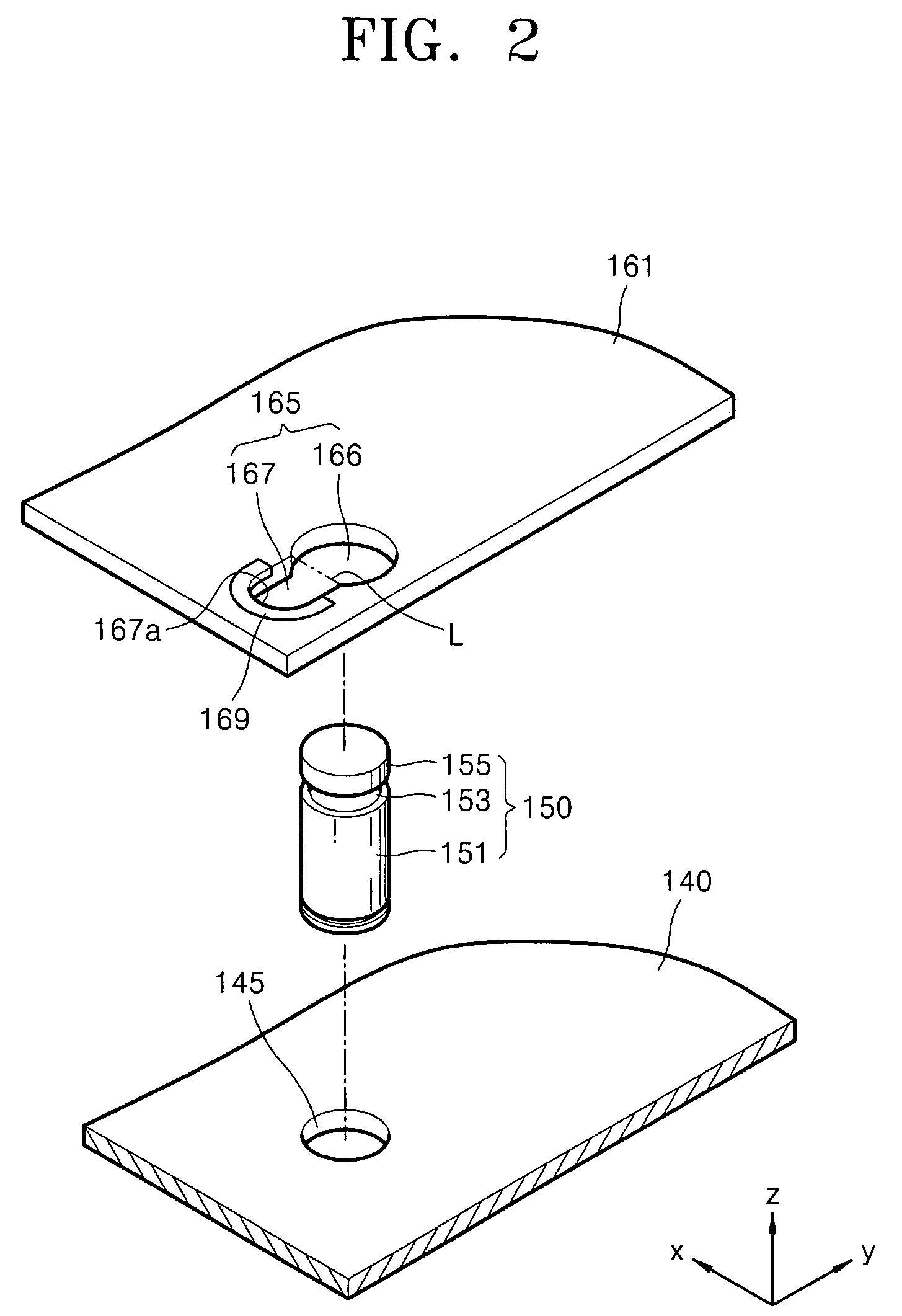
The present invention provides a fixing structure and a plasma display module that overcome the disadvantages of the related art. The fixing structure includes a circuit board with a hole and a board mounting member with an insertion portion that fits into the hole, allowing for efficient alignment and securing of the hole with the boss. The plasma display module includes a plasma display panel, a chassis base, and a circuit unit with multiple circuit boards that have U-shaped board mounting holes and boss holes. The board mounting members are coupled between the chassis base and the circuit boards, with the insertion portion fitting into the hole of the board mounting hole. The module also includes bosses and boss screws for secure attachment to the chassis base. The technical effects of the invention include efficient alignment and securing of the hole with the boss, and improved stability and reliability of the plasma display module.

Problems solved by technology

However, manufacturing a boss with a step may require additional manufacturing processes, thereby increasing manufacturing costs.
Further, movement of the circuit board above the boss in order to facilitate exact fit between the circuit board hole and the boss step may increase processing time.

Method used


Image

  • Fixing structure of circuit board and display module comprising the same
  • Fixing structure of circuit board and display module comprising the same
  • Fixing structure of circuit board and display module comprising the same

Examples


Embodiment Construction

[0027]Korean Patent Application No. 10-2006-0035747, filed on Apr. 20, 2006, in the Korean Intellectual Property Office, and entitled: “Fixing Structure of Circuit Board and Display Apparatus Comprising the Same,” is incorporated by reference herein in its entirety.

[0028]The present invention will now be described more fully hereinafter with reference to the accompanying drawings, in which exemplary embodiments of the invention are illustrated. The invention may, however, be embodied in different forms and should not be construed as limited to the embodiments set forth herein. Rather, these embodiments are provided so that this disclosure will be thorough and complete, and will fully convey the scope of the invention to those skilled in the art.

[0029]In the figures, the dimensions of elements and regions may be exaggerated for clarity of illustration. It will also be understood that when a layer or element is referred to as being “on” another layer, element or substrate, it can be d...


PUM


Abstract

A fixing structure for a circuit board includes at least one board mounting hole in the circuit board, the board mounting hole having a guide hole and an insertion hole, and at least one board mounting member inserted through the board mounting hole, the board mounting member having a main body, a cover, and an insertion portion therebetween, wherein the insertion portion has a cross-sectional area smaller than either of the main body or the cover and is capable of fitting in the insertion hole of the board mounting hole.

Description

BACKGROUND OF THE INVENTION[0001]1. Field of the Invention[0002]The present invention relates to a fixing structure of a circuit board and a plasma display module including the same. More particularly, the present invention relates to a fixing structure capable of securing a circuit board to a chassis base of a plasma display module at a predetermined uniform distance.[0003]2. Description of the Related Art[0004]In general, various kinds of circuit boards may be employed in a plasma display module. In particular, at least one conventional circuit board may be mounted on a chassis base of a plasma display module to supply electric power to the plasma display module and to control electric signal transmission within the plasma display module.[0005]The conventional circuit board may be attached to the chassis base by at least one screw coupled to a boss. More particularly, the circuit board may include a hole aligned with a boss of a chassis base, so a screw may be coupled to the boss ...

Claims


Application Information

Patent Timeline
Patent Type & Authority Patents(United States)
IPC IPC(8): H01R4/66
CPCH05K1/0215H05K1/116H05K1/119H05K7/142H05K1/0213H05K2201/09463H05K2201/09854H05K2201/10863Y10S439/947H01J11/34H01J11/20
Inventor BANG, WON-KYUKIM, MYOUNG-KON
Owner SAMSUNG SDI CO LTD
Learn More