
Continuous casting mold for liquid metals, especially for liquid steel

Inactive Publication Date: 2008-04-29
FEHLEMANN GEREON
View PDF13 Cites 4 Cited by
  • Summary
  • Abstract
  • Description
  • Claims
  • Application Information

AI Technical Summary

Benefits of technology

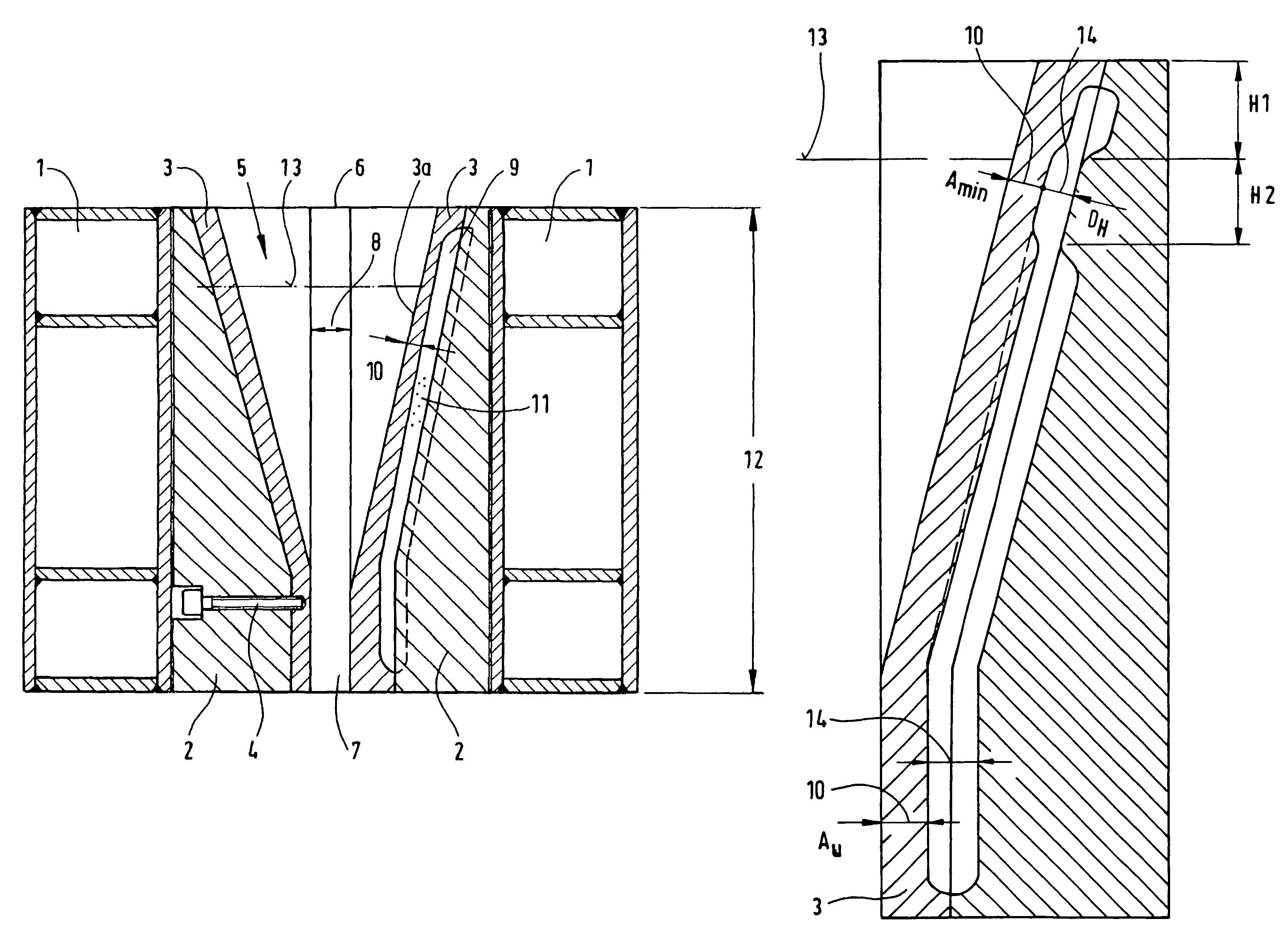
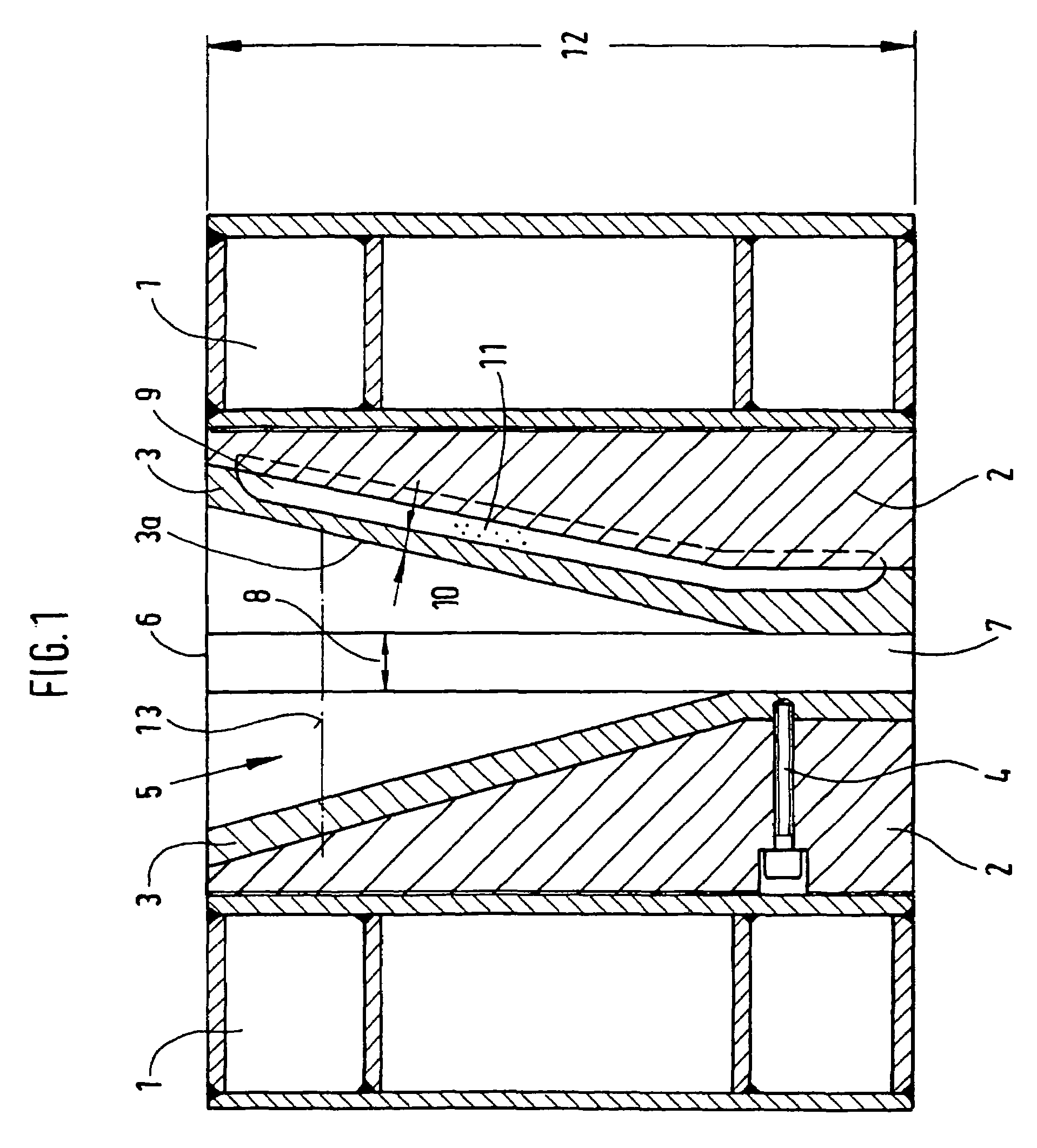
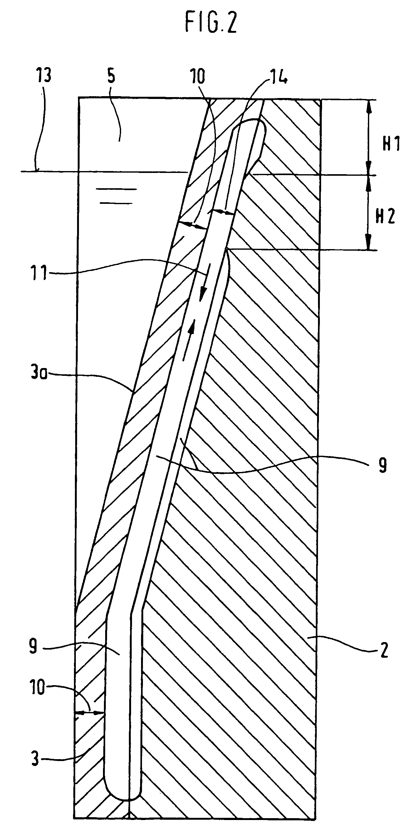
[0006]In accordance with the invention, this objective is achieved by varying the thickness of the copper plates between the coolant and the hot side of the copper plates over the width and / or over the height. In this way, the hot-side temperature can be evened out over the width of the mold, and the significant temperature drop below the meniscus region can be reduced over the height of the mold.
[0014]Special molds for casting thin slabs are used in CSP plants. Here it is advantageous that a funnel mold can be used and that the width section with the greatest distance of the coolant channel from the hot-side surface of the copper plate has a length of 50-80% of the width region in the funnel.

Problems solved by technology

Despite these advantages, the cassette mold has the disadvantage of a high hot-side temperature in the meniscus region with a sharp temperature drop below it.
This results in a high load of the strand shell on the cast strand and thus the danger of surface defects.
In addition, an uneven slag film thickness develops prematurely due to the significantly different hot-side temperature in the upper region of the mold.
Furthermore, it must be assumed on the basis of experience that different mold temperatures are also present along the cast width, which can have a negative effect on the service life of the mold and the surface quality of the cast strand.

Method used


Image

  • Continuous casting mold for liquid metals, especially for liquid steel
  • Continuous casting mold for liquid metals, especially for liquid steel
  • Continuous casting mold for liquid metals, especially for liquid steel

Examples


Embodiment Construction

[0021]In the continuous casting mold, liquid metals, especially liquid steel, are cast into cast strands with various formats and with billet, bloom, slab, and thin-slab cross sections. Opposing steel charging plates 2 and copper plates 3 that rest against the steel charging plates 2 are mounted inside a water tank 1, e.g., fastened with screws 4 to the steel charging plates 2, which form a cassette. The copper plates 3 bound the casting cavity 5. End plates 7, so-called narrow-side plates, are arranged between the copper plates 3. The thickness 8 of the end plates 7 forms the thickness of the cast strand, or the end plates 7 determine the width of the cast strand by the distance that separates them.

[0022]Coolant channels 9, each of which is provided with an inlet and an outlet, are incorporated in the copper plates 3 at the boundary with the steel charging plates 2.

[0023]In contrast to previous mold copper plates 3, the thickness 10 of the copper plates 3 between the coolant 11 and...


PUM

PropertyMeasurementUnit
Fractionaaaaaaaaaa
Volumeaaaaaaaaaa
Depthaaaaaaaaaa

Abstract

The invention relates to a continuous casting mould for liquid metals, especially for liquid steel, comprising steel charging plates (2) which are surrounded by water reservoirs (1), cassette-type copper plates (3) arranged against the same, end plates (7), if needed, for the thickness and / or the width of the cast billet, and coolant channels (9). The aim of the invention is to take measures to counteract the high temperatures in the meniscus region (13) using appropriate embodiments of the copper plates (3) and / or the steel charging plates (2). To this end, the thickness (10) of the copper plates (3) between the coolant (11) and the hot side (3a) of the copper plates varies along the width (2×L) and / or in terms of the height (12).

Description

CROSS-REFERENCE TO RELATED APPLICATION[0001]This application is a 371 of PCT / EP03 / 03081 filed on Mar. 25, 2003.BACKGROUND OF THE INVENTION[0002]The invention concerns a continuous casting mold for liquid metals, especially liquid steel, with steel charging plates, which are arranged parallel opposite each other to form the casting cross section and are surrounded by water tanks; with cassette-type copper plates, which rest against the steel charging plates and bound the casting cavity; possibly with end plates, which are inserted at the end faces of the casting cavity for establishing the thickness and / or width of the cast strand and close the casting cavity at the end faces; and with coolant channels that connect an inlet with an outlet in the copper plates at their contact surfaces with the steel charging plates.[0003]The specified continuous casting mold is known from DE 195 81 604 T1. A continuous casting mold of this type represents a so-called cassette mold. The cassette mold ...

Claims


Application Information

Patent Timeline
IPC IPC(8): B22D11/00B22D11/04B22D11/055
CPCB22D11/0408B22D11/055
Inventor FEHLEMANN, GEREONSTREUBEL, HANS
Owner FEHLEMANN GEREON
Learn More