
Method and system for matching a hierarchical identifier

a hierarchical identifier and matching technology, applied in the field of electronic design tools, can solve the problems of difficult analysis, user of an hlms may be unable to easily inspect and understand the information produced by the low-level analyzer, and it is difficult to make use of the analyzer output for a designer accustomed to working at the high-level provided by the hlms

Active Publication Date: 2008-04-22
XILINX INC
View PDF55 Cites 17 Cited by
  • Summary
  • Abstract
  • Description
  • Claims
  • Application Information

AI Technical Summary

Benefits of technology

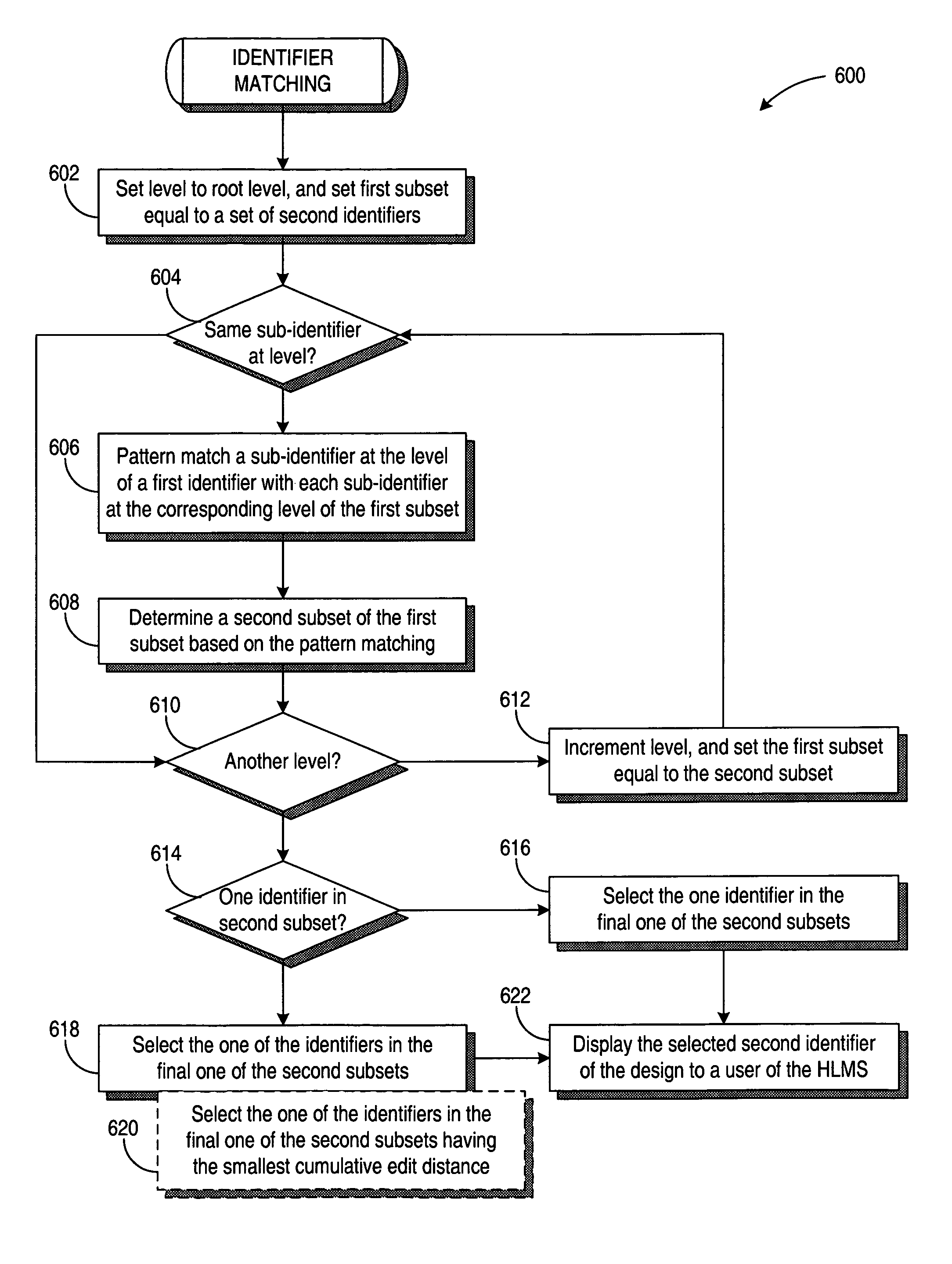
[0007]Various embodiments of the invention provide a method for matching a hierarchical identifier with a block instance of a design in a high-level modeling system. A tree is generated that represents a hierarchy of the block instances of the design in the high-level modeling system. The tree includes a respective node for each block instance of the design, and the respective node includes a first name of the block instance. The first name of each node in a first subset of each level of the hierarchy is pattern matched with a second name at a corresponding level o

Problems solved by technology

In many instances, these tools change the names of the components or elements in the design, which makes analysis challenging if the user is used to working with high-level designs.
However, the user of an HLMS may be unable to easily inspect and understand the information produced by the low-level analyzers.
The difficulties arise because a low-level analyzer expresses the output information using the names it received as input or as may have been modified by the analyzer.
Since the names presented by the low-level analyzer may be different from the names in the high-level modeling system, it may be difficult to make use of the analyzer output for a designer accustomed to working at the high-level provided by the HLMS.

Method used


Image

  • Method and system for matching a hierarchical identifier
  • Method and system for matching a hierarchical identifier
  • Method and system for matching a hierarchical identifier

Examples


Embodiment Construction

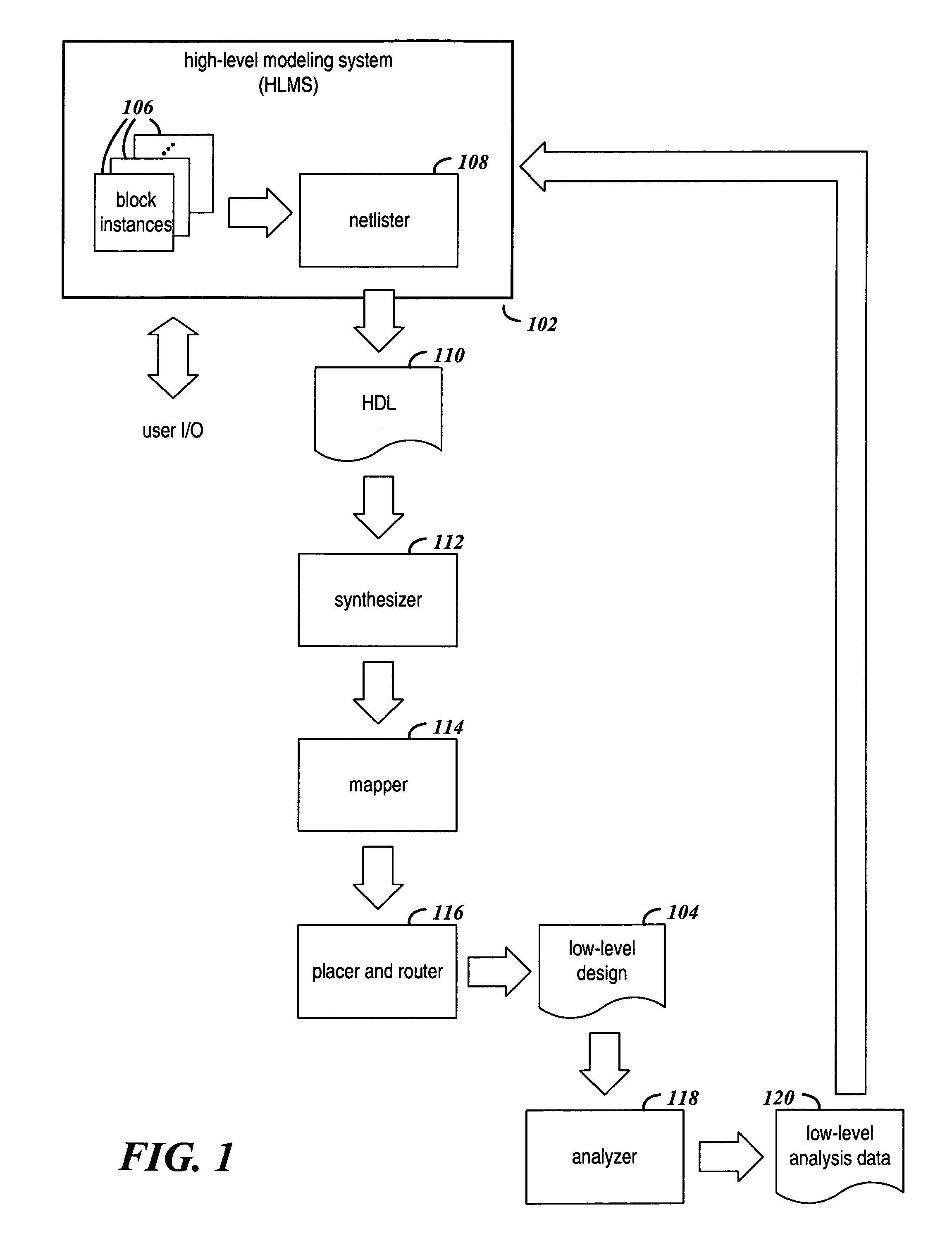
[0017]FIG. 1 is a flow diagram that shows the transformation of a high-level design in a high level modeling system (HLMS) 102 to a low-level design 104. The design information for the high-level design of an electronic circuit design may be created in the HLMS 102 by a user selecting and connecting various design block instances 106.

[0018]A netlister 108 may transform the high-level design of block instances 106 into a hardware description language 110 (HDL) representation of the high-level design. The HDL 110 may be processed by a sequence of tools including a synthesizer 112, a mapper 114, and a placer and router 116 to produce the low level design 104. Typically, the low level design 104 extends the hierarchy present in the high-level design by mapping each block instance 106 into a collection of interconnected primitives, such as AND gates, OR gates, and look-up tables.

[0019]An analyzer 118 may determine certain characteristics of the low-level design 104 and report these chara...


PUM


Abstract

A first hierarchical identifier is efficiently matched with a particular hierarchical identifier from a set of second hierarchical identifiers of a design in a high level modeling system. The matching tolerates name changes and additional design details in the hierarchical identifiers. A first sub-identifier at each level of the first hierarchical identifier is pattern matched with each second sub-identifier at a corresponding level of at least one second hierarchical identifier in a respective first subset of the second hierarchical identifiers. The pattern matching may include determining an edit distance between the first and second sub-identifiers. For each of the levels, a respective second subset of the respective first subset is determined in response to the pattern matching. The particular hierarchical identifier is selected from an intersection of all of the second subsets. The particular hierarchical identifier of the design is displayed on a user interface of the high-level modeling system.

Description

FIELD OF THE INVENTION[0001]The present invention generally relates to electronic design tools.BACKGROUND[0002]A high-level modeling system (HLMS) allows a user to assemble, simulate, and debug an electronic circuit design. Some HLMS′, such as the System Generator HLMS from Xilinx, also allow the design to be translated into a hardware description language (HDL).[0003]An electronic circuit design in an HLMS is generally assembled with design blocks. Each block performs a desired function in the design, and instances of the blocks are connected to accomplish the overall function of the design. For user convenience in assembling and manipulating the design, the block instances may be hierarchically arranged or nested such that a block instance may include one or more sub-block instances.[0004]Additional tools are used in transforming the high-level design into a low-level form that is realizable in hardware. These tools provide functions of technology mapping, component placement, and...

Claims


Application Information

Patent Timeline
IPC IPC(8): G06F17/50
CPCG06F17/504G06F17/5077G06F30/3323G06F30/394
Inventor VOGENTHALER, ALEXANDER R.
Owner XILINX INC
Learn More