
Method and systems for dynamic range expansion

a dynamic range and expansion method technology, applied in the field of dynamic range expansion methods and systems, can solve the problems of reducing the useful dynamic range of flow cytometers, limiting the current availability of flow cytometers, and adding noise to the small signal level, so as to increase the dynamic range of the system

Active Publication Date: 2008-04-22
LUMINEX
View PDF18 Cites 119 Cited by
  • Summary
  • Abstract
  • Description
  • Claims
  • Application Information

AI Technical Summary

Benefits of technology

This approach effectively increases the dynamic range of flow cytometry systems by allowing accurate measurement of both low and high fluorescence levels without introducing noise, enhancing the signal-to-noise ratio and the system's discriminatory capabilities.

Problems solved by technology

The DR of currently available flow cytometers is limited by the DR of each individual element in the system (e.g., the major components including the photosensitive detector, analog electronics, and A / D converter).
With commonly available off-the-shelf linear components, the useful dynamic range of flow cytometers is limited to approximately 4 decades (1 to 10,000).
This technique, while seemingly adequate to cover both small and large signal ranges, is disadvantageous in that the electrical gain stage, when inserted in the signal path, adds noise to the small signal level.

Method used


Image

  • Method and systems for dynamic range expansion
  • Method and systems for dynamic range expansion
  • Method and systems for dynamic range expansion

Examples


Embodiment Construction

[0032]Although embodiments are described herein with respect to particles, it is to be understood that the systems and methods described herein may also be used with microspheres, polystyrene beads, microparticles, gold nanoparticles, quantum dots, nanodots, nanoparticles, nanoshells, beads, microbeads, latex particles, latex beads, fluorescent beads, fluorescent particles, colored particles, colored beads, tissue, cells, micro-organisms, organic matter, non-organic matter, or any other discrete substances known in the art. The particles may serve as vehicles for molecular reactions. Examples of appropriate particles are illustrated in U.S. Pat. No. 5,736,330 to Fulton, U.S. Pat. No. 5,981,180 to Chandler et al., U.S. Pat. No. 6,057,107 to Fulton, U.S. Pat. No. 6,268,222 to Chandler et al., U.S. Pat. No. 6,449,562 to Chandler et al., U.S. Pat. No. 6,514,295 to Chandler et al., U.S. Pat. No. 6,524,793 to Chandler et al., and U.S. Pat. No. 6,528,165 to Chandler, which are incorporated...


PUM

PropertyMeasurementUnit
fluorescentaaaaaaaaaa
angleaaaaaaaaaa
fluorescenceaaaaaaaaaa

Abstract

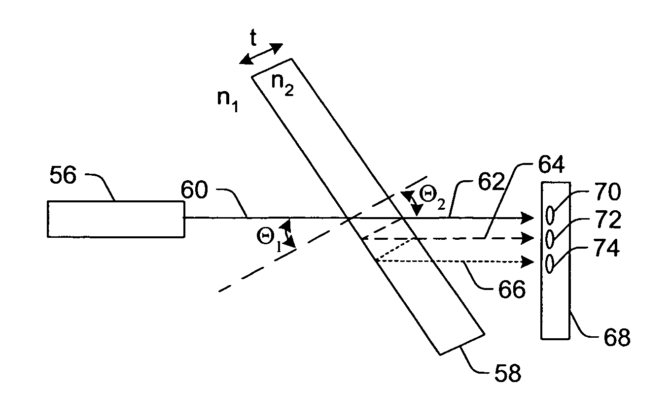
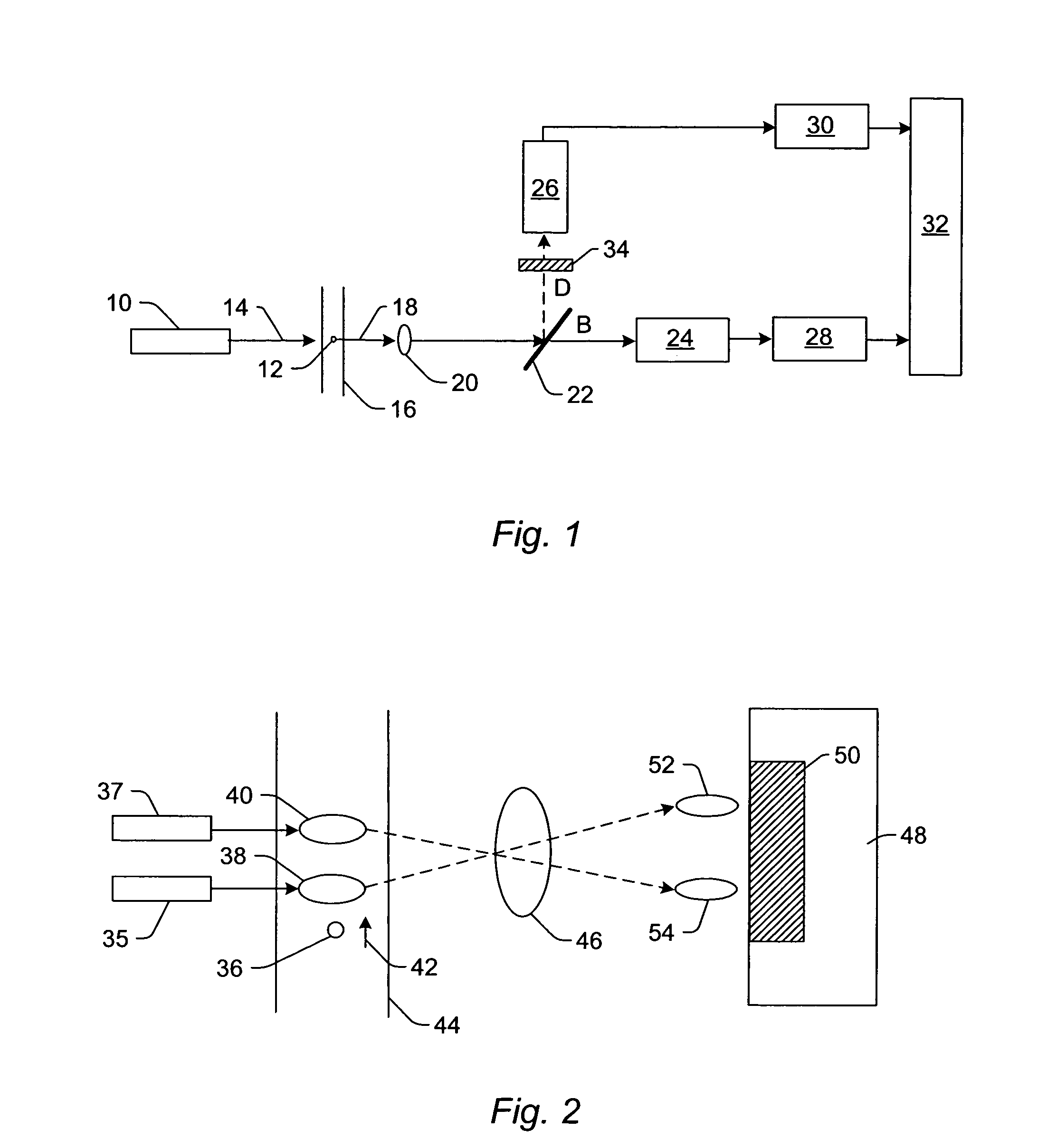
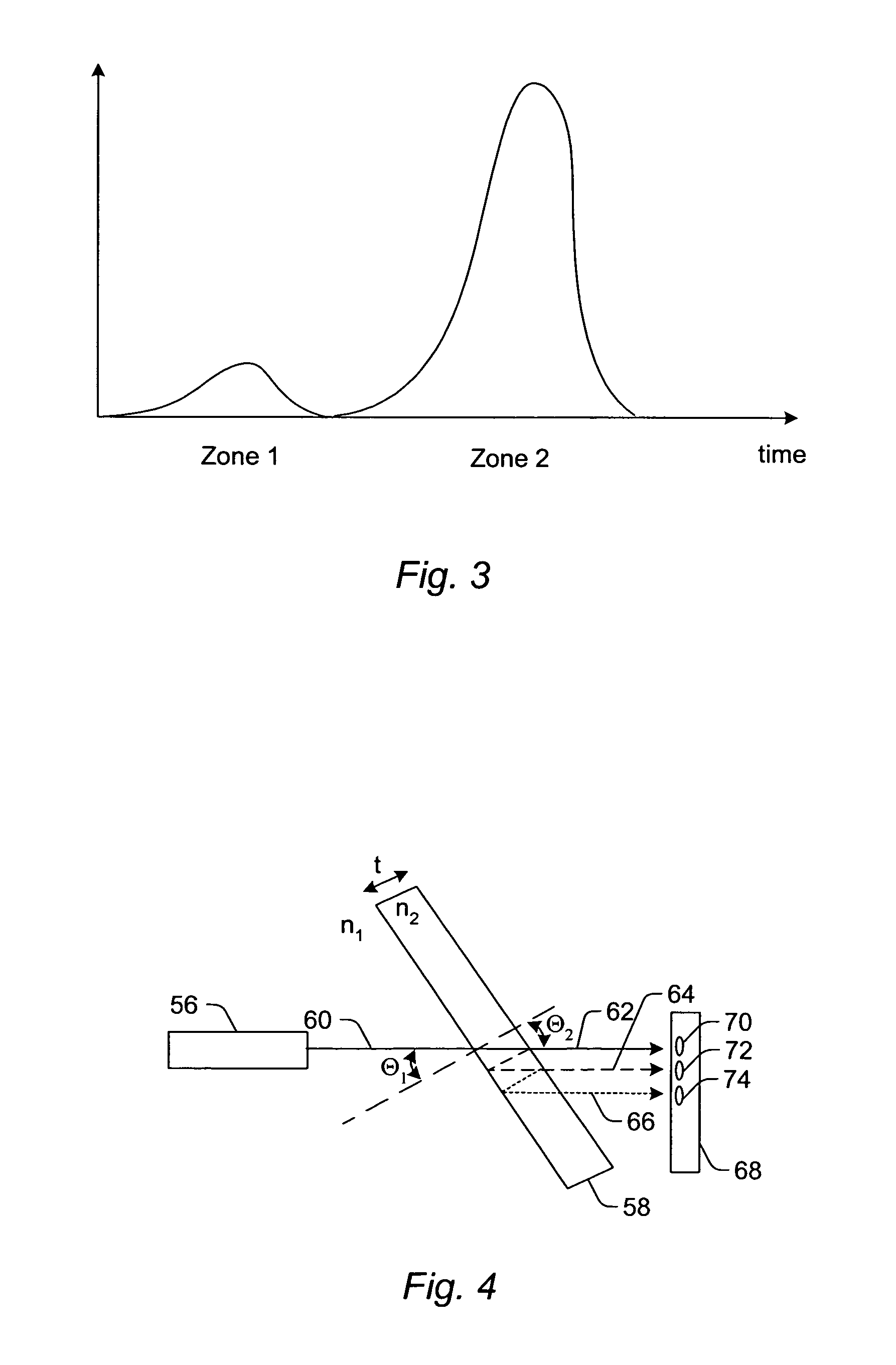
Methods and systems for expanding the dynamic range of a system are provided. One method includes splitting fluorescent light emitted by a particle into multiple light paths having different intensities, detecting the fluorescent light in the multiple light paths with different channels to generate multiple signals, and determining which of the channels is operating in a linear range based on the multiple signals. The method also includes altering the signal generated by the channel operating in the linear range to compensate for the different intensities. Another method includes illuminating a particle in multiple illumination zones with light having different intensities and separately detecting fluorescent light emitted by the particle while located in the multiple illumination zones to generate multiple signals. The method also includes determining which of the signals is located in a linear range and altering the signal located in the linear range to compensate for the different intensities.

Description

PRIORITY CLAIM[0001]This application claims priority to U.S. Provisional Application No. 60 / 536,465 entitled “Methods and Systems for Dynamic Range Expansion,” filed Jan. 14, 2004, which is incorporated by reference as if fully set forth herein.BACKGROUND OF THE INVENTION[0002]1. Field of the Invention[0003]This invention generally relates to methods and systems for dynamic range expansion. Certain embodiments relate to methods and systems for dynamic range expansion in flow cytometry applications.[0004]2. Description of the Related Art[0005]The following descriptions and examples are not admitted to be prior art by virtue of their inclusion within this section.[0006]Generally, flow cytometers can be used to provide measurements of the intensity of fluorescent light emitted by polystyrene beads, human cells, or other discrete substances due to exposure to an excitation source such as a laser as they pass linearly through a flow chamber. In some systems, there are four measurements t...

Claims


Application Information

Patent Timeline
Patent Type & Authority Patents(United States)
IPC IPC(8): G01J3/30F21V9/16G01N21/00G01N21/25G01N15/14
CPCB82Y10/00B82Y20/00G01N15/14G01N21/64G01N15/00
Inventor ROTH, WAYNE D.
Owner LUMINEX
Learn More