System and method for image-based rendering with object proxies

a technology of object proxies and image-based rendering, applied in the field of computer graphics, can solve the problems of increasing the number of calculations and other processing work required to fully render the object, affecting the quality of the object, and speed and cost, and achieve the effect of achieving the intermediate level of rendering quality

Inactive Publication Date: 2008-04-22
MORGAN STANLEY +1
View PDF6 Cites 0 Cited by
  • Summary
  • Abstract
  • Description
  • Claims
  • Application Information

AI Technical Summary

Benefits of technology

[0010]The present invention overcomes each of the above-identified problems and has additional advantages as described herein. The present invention leverages object proxies to provide an intermediate level of rendering quality.
[0020]Rendering based on the use of object proxies according to the present inventions has advantages. First, such rendering with the use of object proxies according to the present invention is faster and less expensive than fully rendering objects based on object geometry data. This is especially true for complex objects with large numbers of polygons. On the other hand, rendering with the use of object proxies according to the present invention provides more surface detail and realism than conventional approaches that render to a billboard. In this way, the present invention allows rendering of one or more objects based on their object proxies to be carried out for display or animation in real-time at an interactive rate even on cheaper graphics hardware.

Problems solved by technology

These demands include realism, speed and cost.
Complex objects, however, can involve a large number of primitives.
This increases the number of calculations and other processing work required to fully render the object.
In such a billboard approach object data is rendered as if it were mapped or tiled on a flat plane or “billboard.” The billboard approach, however, sacrifices realism and geometry detail.
Accordingly, its usefulness is limited to objects viewed from afar unless hundreds of pre-computed texture images are used exceeding the limits of texture hardware.
These approaches are limited, however, in that they cannot deal with concave proxies and their rendering algorithms are not well suited for mixing image-based rendering objects with regular scenes.
Furthermore, the rendering algorithms of these approaches are complex and too slow for many if not all real-time rendering environments.
Thus, the approaches of others to this problem have not been successful in fulfilling the need for a method and system for rendering that provides an intermediate level of rendering quality in between full object rendering and a billboard rendering.

Method used


Image

  • System and method for image-based rendering with object proxies
  • System and method for image-based rendering with object proxies
  • System and method for image-based rendering with object proxies

Examples


example system embodiment

of the Present Invention

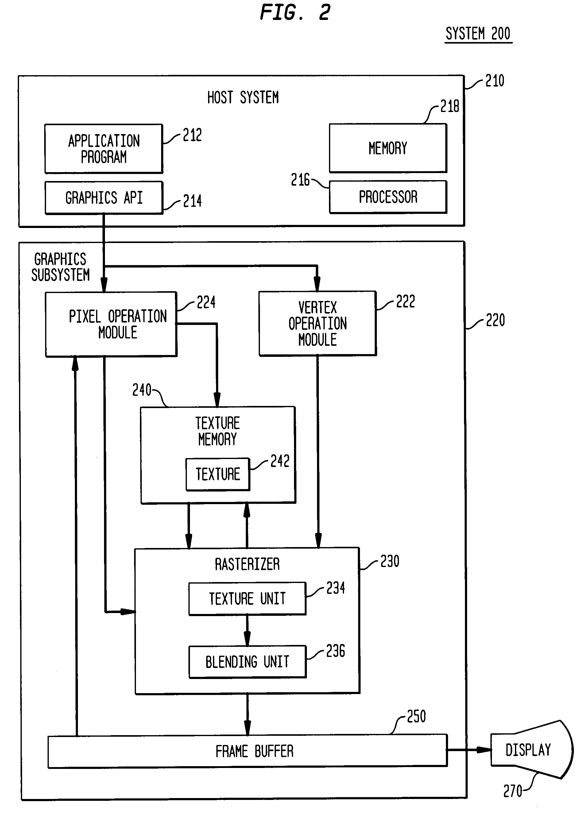
[0055]FIG. 2 illustrates an example graphics system 200 according to an embodiment of the present invention. Graphics system 200 comprises a host system 210, a graphics subsystem 220, and a display 270. Each of these features of graphics system 200 is further described below.

[0056]Host system 210 comprises an application program 212, a hardware interface or graphics API 214, a processor 216, and a memory 218. Application program 212 can be any program requiring the rendering of a computer image. The computer code of application program 212 is executed by processor 216. Application program 212 assesses the features of graphics subsystem 220 and display 270 through hardware interface or graphics API 214. Memory 218 stores information used by application program 212.

[0057]Graphics subsystem 220 comprises a vertex operation module 222, a pixel operation module 224, a rasterizer 230, a texture memory 240, and a frame buffer 250. Texture memory 240 can store one or...

example method embodiments

of the Present Invention

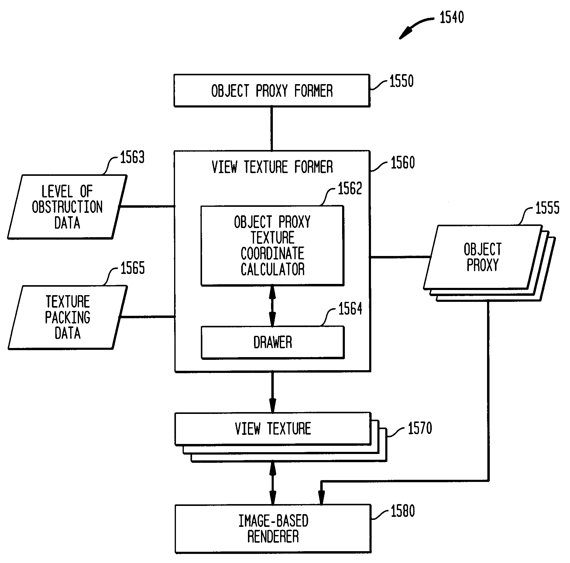
[0060]FIG. 3A illustrates a flowchart of a method 300 for image-based rendering with object proxies according to an embodiment of the invention. As noted above, an object proxy is a simplification of an object boundary that is useful for hardware-accelerated image-based rendering. Image-based rendering with object proxies according to the present invention makes it possible both to render more image-based objects in a single computer generated scene and to render these image-based objects using fewer views / textures than conventional image-based rendering schemes.

[0061]In an embodiment, method 300 operates as follows. A viewing direction for rendering an object is chosen. Next, at least two pre-computed view textures and a pre-computed object proxy associated with the chosen viewing direction are selected. Blending weights are assigned to each of the selected view textures. The object is then drawn to a buffer using the selected object proxy, the selected view...


PUM


Abstract

A system and method for rendering with an object proxy. In one embodiment, a method includes forming a set of view textures corresponding to a set of viewing directions; selecting a viewing direction for rendering; selecting at least two view textures from the formed set based on the selected viewing direction; and rendering the object proxy at the selected viewing direction. The rendering step includes applying texture from the selected view textures onto the selected object proxy. The view texture set forming step includes: calculating texture coordinates for the object proxy based on the level of obstruction at different portions of the object proxy and texture packing data; and drawing portions of the object based on the level of obstruction data for the object proxy and based on the texture packing data to obtain a view texture at the selected viewing direction.

Description

CROSS-REFERENCE TO RELATED APPLICATIONS[0001]This application is related to a commonly-owned, application by Mech, “System and Method for Forming an Object Proxy,” U.S. application. Ser. No. 10 / 197,822, filed Jul. 19, 2002, now U.S. Pat. No. 6,813,642, and incorporated by reference herein in its entirety.BACKGROUND OF THE INVENTION[0002]1. Field of the Invention[0003]The present invention relates to computer graphics.[0004]2. Related Art[0005]A wide variety of applications rely on computer graphics to generate images. An image is made up of an array of picture elements (pixels) and can be displayed on a display unit, such as, a monitor, screen, or cathode ray tube. Images often include graphical representations of objects. Many different types of computing devices with graphics capabilities are used to generate images. Such computing devices use graphics processing. A combination of software, firmware and / or hardware is used to implement graphics processing. For example, graphics pr...

Claims


Application Information

Patent Timeline
Patent Type & Authority Patents(United States)
IPC IPC(8): G09G5/00G06T15/20
CPCG06T15/04G06T15/205
Inventor MECH, RADOMIR
Owner MORGAN STANLEY
Why Eureka
Try Eureka