
Crowd control system for a loader

a control system and loader technology, applied in agricultural machines, applications, instruments, etc., can solve the problems of increasing the actuator force, the linkage of the loader, and increasing the cycle time, so as to reduce the crowd force and reduce the motive power

Active Publication Date: 2008-04-08
DEERE & CO
View PDF13 Cites 8 Cited by
  • Summary
  • Abstract
  • Description
  • Claims
  • Application Information

AI Technical Summary

Benefits of technology

[0005]It is an object of the present invention to provide an improved crowd control system for a loader equipped with a torque converter. More specifically, the present invention automatically reduces crowd force against the loader linkage actuators during a loading operation by reducing the motive power transferred through the torque converter.
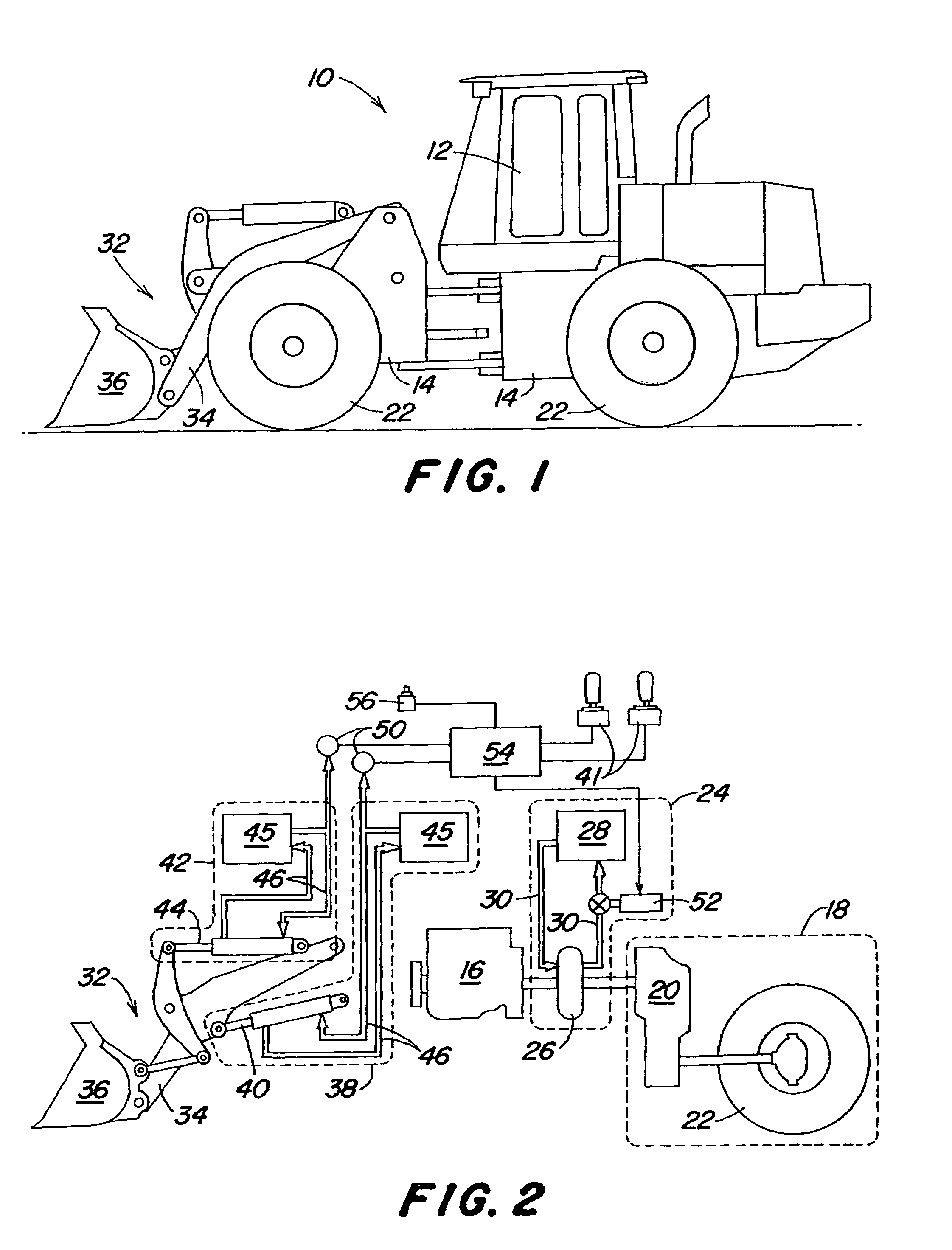
[0006]The torque converter is supplied with lubrication fluid by a lubrication circuit, typically the lubrication system of the transmission. The lubrication fluid is utilized by the torque converter to transfer power from the engine to the transmission. By controlling the supply of lubrication fluid to the torque converter when crowd force is undesired, the magnitude of power that the torque converter is able to transfer can be reduced, thereby reducing crowd on the loader linkage. The illustrated embodiment makes use of a proportional control valve connected in the return flow of the lubrication fluid between the lubrication circuit and the torque converter to control lubrication fluid flow for this purpose.

Problems solved by technology

The motive force of the vehicle acting on the pile during this operation generates a crowd force against the loader linkage, increasing the actuator force required to raise the loader linkage and subsequently increasing the cycle time.
In this situation, the operator is required to manually reduce the vehicle motive force in order to reduce crowd on the loader linkage, further increasing cycle time.
The increased cycle time and operator effort attributed to crowd force diminishes overall productivity.

Method used


Image

  • Crowd control system for a loader
  • Crowd control system for a loader

Examples


Embodiment Construction

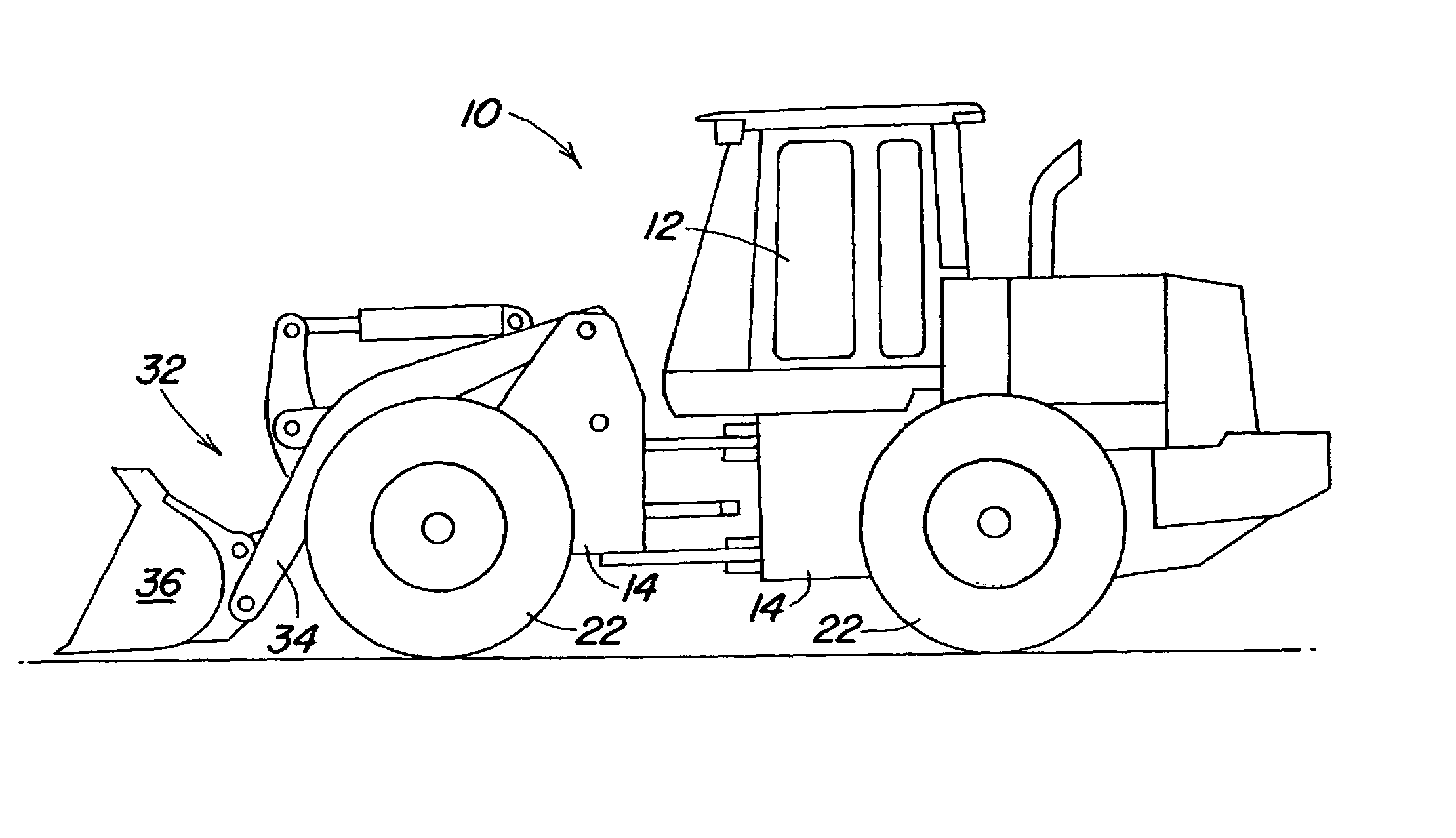
[0010]FIG. 1 illustrates a self-propelled work vehicle, such as a loader 10. An operator controls the functions of the vehicle from an operator's station 12. The loader 10 has a frame 14, and an engine 16 that powers the vehicle. The engine 16 powers a drive unit 18 comprising a transmission 20 connected to ground engaging wheels 22 that support and propel the vehicle. Although the present invention is illustrated as being used on a loader 10 with ground engaging wheels 22 as ground engaging portions, it could also be used on loaders having ground engaging belts or tracks as the ground engaging portions.

[0011]In the embodiment illustrated in FIG. 2, a fluid coupling 24 couples the engine 16 and the transmission 20 to one another. More specifically, the fluid coupling 24 in the illustrated embodiment includes a torque converter 26. The torque converter 26 is supplied with lubrication fluid 30 by a lubrication circuit 28. The lubrication fluid 30 is utilized by the torque converter 26...


PUM


Abstract

A work vehicle comprising a motor, a drive unit for driving a ground engaging portion, a torque converter for variably transferring power from the motor to the ground engaging portion, a lubrication circuit for providing lubrication fluid to the torque converter, and a control valve located between the torque converter and the lubrication circuit. The work vehicle further having a linkage for performing a work function, an actuator to controllably move the linkage, a sensor coupled to the actuator to sense a force opposing the actuator, and a controller in communication with the sensor and the control valve. The controller is adapted to command a crowd reduction in response to the sensed force opposing the linkage, whereby the pressure of the lubrication fluid provided to the torque converter is reduced.

Description

FIELD OF THE INVENTION[0001]The present invention relates to a system for automatically reducing crowd force against loader linkage actuators during a loading operation by reducing the motive power transferred through a torque converter.BACKGROUND OF THE INVENTION[0002]Loaders are used to lift and move bulk materials. A loader comprises a self-propelled vehicle having a loader linkage and associated actuators for controllably moving the loader linkage. Such loaders may be provided with wheels or endless tracks for propulsion. A typical work cycle for a loader involves loading material from a pile into the loader bucket, then moving the vehicle to dump the material at a new location, and then repeating. During the bucket loading operation, it is customary for the loader boom be lowered and for the loader bucket to be driven into the pile by the forward movement of the vehicle.[0003]The motive force of the vehicle acting on the pile during this operation generates a crowd force agains...

Claims


Application Information

Patent Timeline
Patent Type & Authority Patents(United States)
IPC IPC(8): G06F7/70E02F3/43E02F9/20
CPCE02F3/435E02F9/2004E02F9/2029
Inventor PORTER, THOMAS ALAN
Owner DEERE & CO
Learn More