
Seat belt retractor

a seat belt and retractor technology, applied in the field of seat belt retractors, can solve the problems of large load applied to seat belts, difficult to provide stable ea load, and difficult to set an arbitrary ea load regardless of the axial length, so as to achieve stable ea load, stable ea load, and simple and inexpensive ea mechanism with variable ea load

Inactive Publication Date: 2008-04-08
JOYSON SAFETY SYST JAPAN KK
View PDF17 Cites 13 Cited by
  • Summary
  • Abstract
  • Description
  • Claims
  • Application Information

AI Technical Summary

Benefits of technology

[0031]The energy-absorption member may be attached to a conventional seat belt retractor to form the seat belt retractor, thereby making the EA mechanism with variable EA load simple and inexpensive. It is possible to adjust the EA load through changing a pitch of the screwed part of the stopper relative to the locking base or changing a shape of the energy-absorption member, thereby making it easy to adjust the EA load. It is arranged such that the energy-absorption member sequentially deforms in a shear mode, thereby stabilizing the EA load.
[0032]In the second aspect of the present invention, the energy-absorption member is formed in one of the column, prism, and tabular shape. Accordingly, the EA mechanism with variable EA load has a simple structure, thereby reducing cost of production of the EA mechanism.
[0033]In the third aspect of the present invention, the torsion bar and the energy-absorption member are independently disposed, thereby making it easy to adjust the EA load.
[0034]In the fourth aspect of the present invention, the cutter cuts the energy-absorption member, thereby stabilizing cutting load of the energy-absorption member. Accordingly, it is possible to stabilize the EA load and absorb the kinetic energy of the passenger efficiently. When the stopper rotates relative to the locking base, the energy-absorption member is cut without rotating the cutter, thereby stabilizing the cutting load of the energy-absorption member. The cutter for cutting the energy-absorption member is formed separately from the stopper, so that the cutter is formed of an optimum material for cutting the energy-absorption member regardless of a material of the stopper.
[0035]In the fifth aspect of the present invention, the cutter has the sharp edge (cutting blade), thereby stabilizing the cutting load of the energy-absorption member.

Problems solved by technology

Therefore, large load is applied to the seat belt due to kinetic energy of the passenger.
For this reason, it is possible to change the EA load within a limited range, and it is difficult to set an arbitrary EA load regardless of the axial length of the second torsion bar.
In addition to the complex shapes and structures of the EA plate and the EA mechanism, it is necessary to from the controller through local curing, thereby making it difficult to provide stable EA load.
In the EA mechanism made by the cutting disclosed in Japanese Patent Publication (Kokai) No. 2000-43677, it is difficult to provide constant stable EA load through the cutting of the inner circumference of the stopper ring.

Method used


Image

  • Seat belt retractor
  • Seat belt retractor
  • Seat belt retractor

Examples


Embodiment Construction

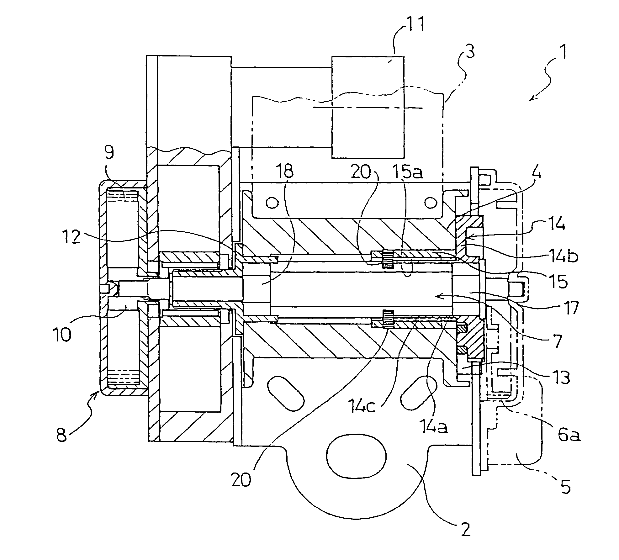
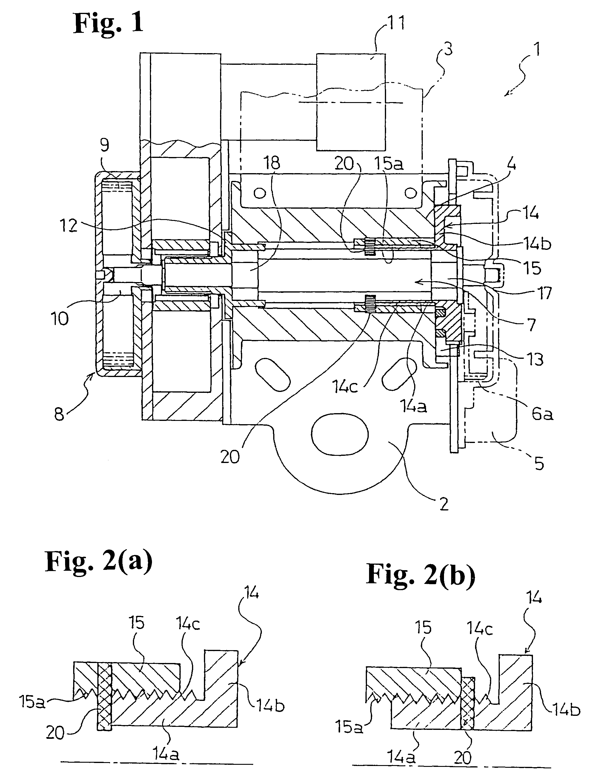
[0041]Hereunder, embodiments of the present invention will be described with reference to the accompanying drawings. FIG. 1 is a sectional view of a seat belt retractor according to an embodiment of the present invention. In the following description, components same as those of a conventional seat belt retractor shown in FIG. 5 are indicated by the same reference numerals, and their explanations are omitted. Right and left in the description represent right and left in the drawings.

[0042]As shown in FIG. 1, in a seat belt retractor according to the embodiment, a stopper 15 extends leftward from a left end of a shaft 14a of a locking base 14 in a normal state. On the extended portion of the stopper 15, a predetermined number of columnar energy-absorption pins 20 are disposed on a circumference of the stopper 15 with an equal interval and protrude inwardly in a radial direction as energy-absorption members (EA members). The energy-absorption pins 20 are disposed separately from a tor...


PUM


Abstract

A seat belt retractor includes a spool for winding a seat belt; a lock mechanism having a locking member for rotation with the spool in a normal state and for stop-rotation in a seat belt withdrawal direction in an emergency state; a torsion bar disposed between the spool and the locking member for absorbing energy of a passenger when the spool rotates in the seat belt withdrawal direction relative to the locking member in the emergency state; a stopper screwed in a shaft of the locking member to be movable in an axial direction along the shaft of the locking member when the spool rotates relative to the locking member; and an energy-absorption member disposed on one of the stopper and the locking member for deforming in a shear mode when the stopper moves in the axial direction along the shaft of the locking member.

Description

BACKGROUND OF THE INVENTION AND RELATED ART STATEMENT[0001]The present invention relates to a seat belt retractor installed in a vehicle such as an automobile for retracting and withdrawing a seat belt. More specifically, the present invention relates to a seat belt retractor with an energy absorption mechanism (hereafter referred to as EA mechanism) for absorbing energy applied to a passenger moving due to inertia. The energy is absorbed by the seat belt when withdrawal of the seat belt is prevented in an emergency situation such as a crash when a large deceleration force is applied on a vehicle while the passenger is wearing the seat belt.[0002]A conventional seat belt apparatus installed in a vehicle such as an automobile comprises a seat belt retractor for retracting a seat belt, a seat belt retractable from the seat belt retractor and having an end fixed to a vehicle body, a buckle fixed to the vehicle body, and a tongue for slidably inserting the seat belt and engaging the buc...

Claims


Application Information

Patent Timeline
Patent Type & Authority Patents(United States)
IPC IPC(8): B60R22/28B60R22/36B60R22/46
CPCB60R22/28B60R2022/287
Inventor HIRAMATSU, KOJI
Owner JOYSON SAFETY SYST JAPAN KK
Learn More