
Methods and apparatus for measuring capillary pressure in a sample

a capillary pressure and sample technology, applied in the field of methods and apparatus for measuring parameters in samples, can solve the problems of significant errors in the measurement of the capillary pressure curve, high cost, and rapid method of mercury intrusion, and achieve the effects of reducing vibration and frictional heating, reducing the radius of rotating parts, and increasing the signal-to-noise ratio

Active Publication Date: 2008-04-01
GREEN IMAGING TECH
View PDF13 Cites 60 Cited by
  • Summary
  • Abstract
  • Description
  • Claims
  • Application Information

AI Technical Summary

Benefits of technology

This approach allows for rapid, accurate measurement of capillary pressure curves with fewer data points, reducing measurement time by a factor of 15 and enabling the use of less expensive, desktop centrifuges and MRI systems, while maintaining the outlet boundary condition and accommodating friable samples.

Problems solved by technology

The mercury intrusion method is rapid, but it is destructive, and the mercury / vacuum system does not represent the wettability of reservoir system.
The porous plate method is a direct and accurate technique, but is extremely time-consuming, since the equilibrium time can range from a week to months per pressure point.
It is however well known that many problems exist with the traditional method, ranging from fundamental concerns about the validity of the underlying theory to uncertainty over how to treat the experimental data.
These assumptions are known to lead to significant errors in the measurement of the capillary pressure curve.
In addition, these three conditions can not be simultaneously satisfied.
For high capillary pressures, the experiment requires a very high rotation speed, which is likely to lead to a violation of the third assumption (capillary pressure is zero at the outlet).
Traditional centrifuge methods for capillary pressure determination are time consuming and special instrumentation is required for the experiment.
The experiment requires a very expensive ultracentrifuge with precise speed control over a wide range of speeds.
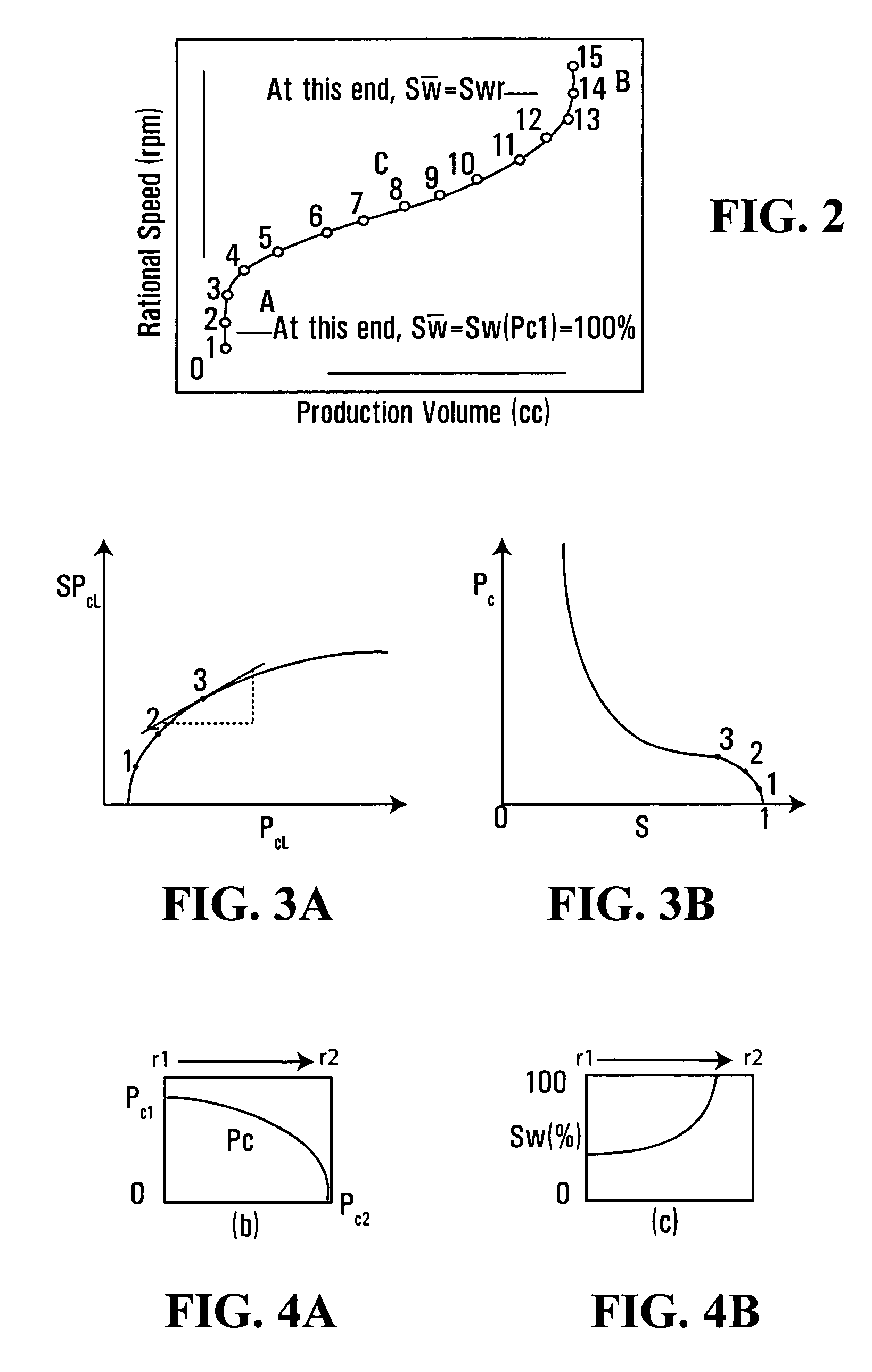
A complete capillary pressure curve usually requires about 15 speeds (15 data points) and may take one to several days to acquire, and therefore obtaining a capillary pressure curve is a relatively slow process.
Another drawback of this conventional method is that it requires a special centrifuge which is capable of providing a wide range of angular velocities and therefore the centrifuge is relatively expensive.
This survey revealed many problems with respect to designing and performing a centrifuge experiment and interpreting the experimental data.
For low permeability samples, the limit on the highest rotational speed of centrifuge rotor may result in the loss of data on residual wetting phase saturation.
Unfortunately, the requirement for minimum and maximum rotational speed results in a serious gravity effect and the violation of the outlet boundary condition, respectively, as discussed above.
Therefore, the traditional centrifuge technique has a number of problems which would be desirable to solve.

Method used


Image

  • Methods and apparatus for measuring capillary pressure in a sample
  • Methods and apparatus for measuring capillary pressure in a sample
  • Methods and apparatus for measuring capillary pressure in a sample

Examples


Embodiment Construction

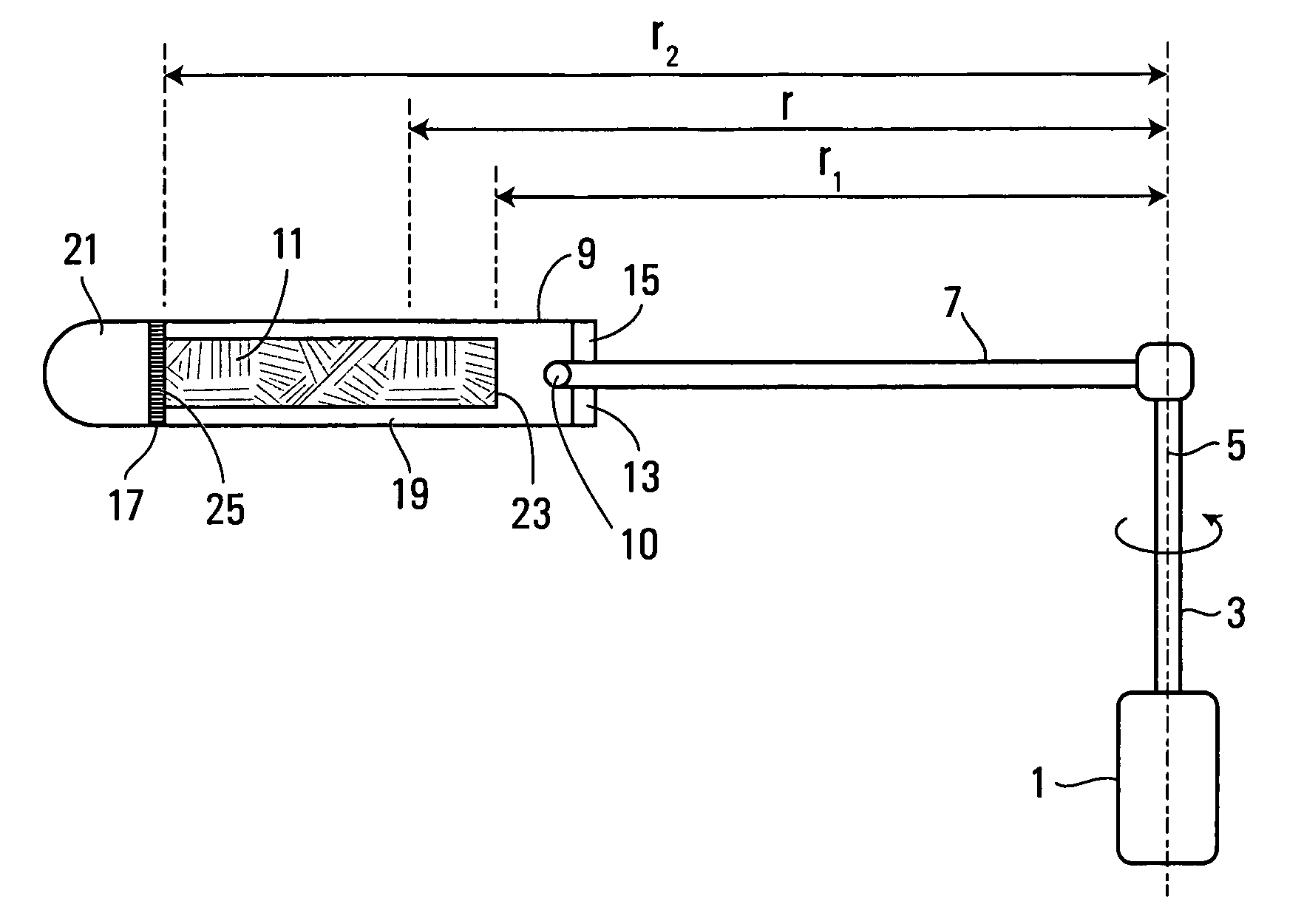
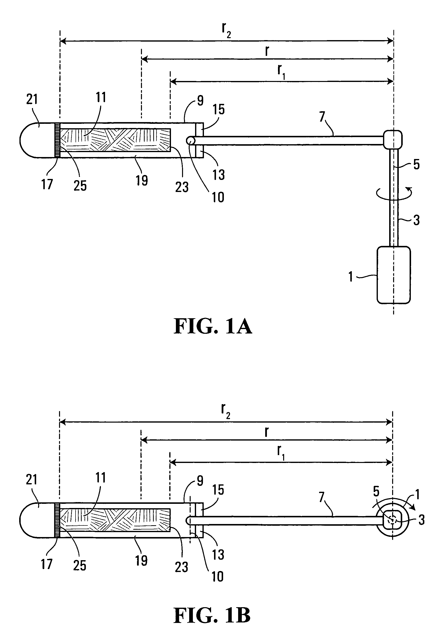
[0107]FIGS. 1a and 1b show a schematic diagram of a centrifuge for use in spinning a sample as part of a capillary pressure measurement, as described above, and which may be used in apparatus and methods of embodiments of the invention. The centrifuge comprises a motor 1 having a shaft 3 which rotates about a rotational axis 5, an arm 7 extending from the shaft 3 and a sample holder 9 pivotally connected to the arm 7 about a pivotal connection point 10 at the end 15 of the arm, so that the sample holder is free to swing up and down. The sample holder comprises a removable sealed end part or closure 13 at the inner end 15 and a porous plate 17 which divides the interior of the sample holder into a first chamber 19 for containing a porous sample and a second chamber 21 at the distal end thereof for collecting liquid 22 expelled from the sample through the porous plate 17.

[0108]The sample has an inlet face 23 spaced at a distance r1 from the rotational axis 5 and an outlet face 25 spac...


PUM


Abstract

A method and apparatus are provided for measuring a parameter such as capillary pressure in porous media such as rock samples. The method comprises mounting a sample in a centrifuge such that different portions of the sample are spaced at different distances from the centrifuge axis, rotating the sample about the axis, measuring a first parameter in the different portions of the sample, and determining the value of a second parameter related to the force to which each portion is subjected due to rotation of the sample. In one embodiment, the first parameter is relative saturation of the sample as measured by MRI techniques, and the second parameter is capillary pressure.

Description

CROSS-REFERENCE TO RELATED APPLICATIONS[0001]This application claims priority from U.S. Patent Application Ser. No. 60 / 622,784 filed on 29 Oct., 2004.FIELD OF THE INVENTION[0002]The present invention relates to methods and apparatus for measuring parameters in samples, and in particular, but not limited to measuring capillary pressure or other parameters in porous media, such as rock samples.BACKGROUND OF THE INVENTION[0003]Capillary pressure curves are widely used in material, soil and environmental sciences, and especially in the petroleum industry. Capillary pressure curves provide critical information frequently used in the assessment of the economic viability of oil reservoir development.[0004]The two most important characteristics of a reservoir core are the porosity and permeability. These are closely followed by the in situ oil saturation, and the capillary pressure. While a slightly more esoteric quantity than the first three, the capillary pressure is fundamental to reserv...

Claims


Application Information

Patent Timeline
Patent Type & Authority Patents(United States)
IPC IPC(8): G01V3/00
CPCG01N24/08G01R33/44G01N24/081G01R33/54G01N2015/0813
Inventor CHEN, QUANBALCOM, BRUCE
Owner GREEN IMAGING TECH
Learn More