
Light source device and projector

a light source device and projector technology, applied in the direction of point-like light sources, lighting and heating apparatuses, instruments, etc., can solve the problems of difficult to fix the lead wire to the reflector, reduce the light utilization efficiency, and reduce the reliability of products, so as to improve the light utilization efficiency and facilitate the incorporation

Inactive Publication Date: 2008-03-18
SEIKO EPSON CORP
View PDF16 Cites 9 Cited by
  • Summary
  • Abstract
  • Description
  • Claims
  • Application Information

AI Technical Summary

Benefits of technology

The present invention provides a light source device that can reliably fix a lead wire without decreasing light utilization efficiency. The light source device includes a light-emitting tube and a reflector with a concave reflecting surface. The lead wire extends from one of the sealing portions of the light-emitting tube and projects towards the reflector. The lead wire is bent along the shape of the opening edge of the reflector to securely fix it. The fold-down portion of the lead wire is designed to easily and reliably fix the lead wire to the reflector. The light source device can be incorporated into apparatuses such as a projector without compromising its reliability. The reflector can be designed without a hole for fixing the lead wire, avoiding a decrease in light utilization efficiency. The light source device can also include a sub-reflecting mirror to increase light utilization efficiency. Overall, the light source device provides a reliable and efficient solution for fixing the lead wire.

Problems solved by technology

This reduces light utilization efficiency, thereby resulting in illumination loss.
In this case, it is difficult to fix the lead wire to the reflector.
If the lead wire is not fixed to the reflector reliably, the lead wire has possibility of falling off from the welding portion when, for example, the lead wire is connected to the connection terminal for an external power source.
In addition, the possibility that the light-emitting tube is broken or damaged by the applied load occurs to decrease built-in characteristics or reliability of the light source device.

Method used


Image

  • Light source device and projector
  • Light source device and projector
  • Light source device and projector

Examples


Embodiment Construction

[0037]An exemplary embodiment according to aspects of the present invention will be described below with reference to the accompanying drawings.

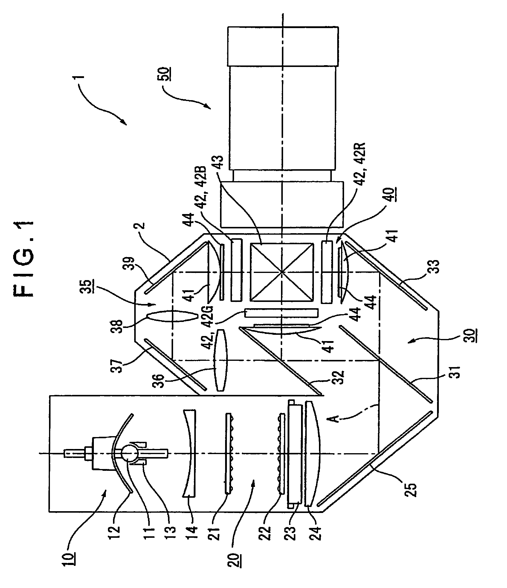
[0038]FIG. 1 is a schematic view showing an optical system of a projector 1 according to an exemplary embodiment. The projector 1 is an optical apparatus that can form an optical image by modulating a light beam irradiated by a light source in accordance with image information and project the optical image on a screen in an enlarged manner. The projector 1 can include a light source lamp unit 10 serving as a light source device, a integrator illumination optical system 20, a color separating optical system 30, a relay optical system 35, an optical device 40 and a projection optical system 50. Optical elements of the optical systems 20 through 35 can be housed with the positions thereof being adjusted within an optical components casing 2 where a predetermined illumination optical axis A is set.

[0039]The light source lamp unit 10 can irradiat...


PUM


Abstract

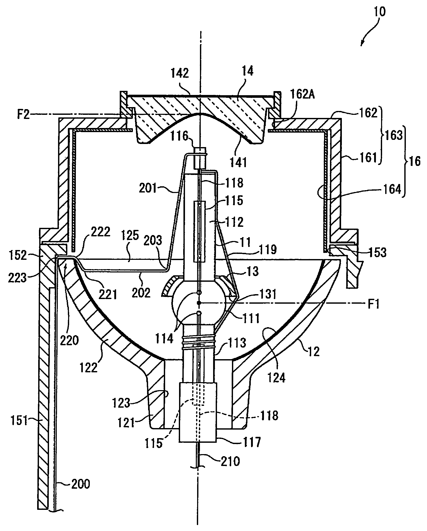
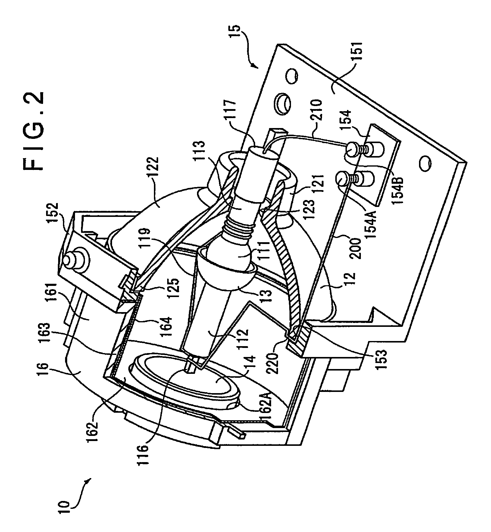
A light source device (10) has: a light-emitting tube (11) including a light-emitting portion (111) that emits a light beam through electrodes (114) and a pair of sealing portions (112, 113) provided on both sides of the light-emitting portion (111) and lead wires (200, 210) for making electrical continuity between the electrodes (114) and an external power source, the lead wires (200, 210) extending from the distal ends of the sealing portions (112, 113), respectively; and a reflector (12) having a concave reflecting surface (124) that emits, from the opening thereof, the light beam irradiated by the light-emitting tube (11) after aligning in a predetermined direction, in which the lead wire (200) extends from the sealing portion (112) on the light beam irradiation front side of the reflector (12) up to the opening end portion (125) of the reflector (12), the lead wire (200) having bent portions (221, 222, 223) in which the lead wire (200) is sequentially bent along the shape of the opening edge portion (125). The lead wire (200) is reliably fixed to the reflector (12) by the spring force between the bent portions (221, 222, 223).

Description

BACKGROUND OF THE INVENTION[0001]1. Field of the Invention[0002]The present invention relates to a light source device and a projector.[0003]2. Description of Related Art[0004]A Projector that modulates a light beam irradiated by a light source in accordance with image information and projects an optical image in an enlarged manner has been widely used, together with a personal computer, for presentation in meetings, academic conferences, exhibitions, or the like. In recent years, it has been used for at-home-movie-viewing.[0005]As a light source device of the projector, a light source obtained by fitting a reflector to a light-emitting tube such as a metal halide lamp, a high-pressure mercury lamp, or halogen lamp is used. An electrical continuity between the light-emitting tube and an external power source is made by a lead wire welded to base caps of sealing portions disposed on both sides of the light-emitting tube.[0006]As disclosed in Jpn. Pat. Laid-Open Publication No. 2003-1...

Claims


Application Information

Patent Timeline
Patent Type & Authority Patents(United States)
IPC IPC(8): G03B21/20F21V7/00F21Y101/00
CPCH01J5/50H01J5/62H01J61/025H01J61/34H01J61/523H01J61/547H01J61/86H04N9/315H04N9/3197G03B21/2026G03B21/00G03B21/14
Inventor TERASHIMA, TORUFUJISAWA, SHOHEI
Owner SEIKO EPSON CORP
Learn More