
Firearm recoil absorbing system

a recoil-absorbing and firearm technology, applied in the field of firearms, can solve the problems of significant recoil, significant recoil, and significant risk of recoil-induced injury to the shooter, and achieve the effect of reducing the recoil of firearms

Inactive Publication Date: 2008-03-18
POFF JR CHARLES
View PDF7 Cites 23 Cited by
  • Summary
  • Abstract
  • Description
  • Claims
  • Application Information

AI Technical Summary

Benefits of technology

[0014]Accordingly, it is an object of the present invention to reduce recoil in firearms and weapons.

Problems solved by technology

Problems relating to recoil when a firearm is discharged have been present in the art for centuries.
As firearms become more powerful and lighter in weight relative to their power, the recoil becomes an increasing problem.
Large caliber weapons produce significant recoil upon firing such that firing such a weapon directly from the shoulder poses a significant risk of recoil-induced injury to the shooter.
If use of these devices is relied upon heavily, the user is forced to carry replacement battery power sources and / or periodically recharge.
Requiring the user to carry non-rechargeable replacement batteries is burdensome.
In addition, requiring the user to effectively find a recharging facility, stop, and recharge is equally undesirable.
While this system is considered useful in generating an electrical charge, it has not been fully integrated with a recoil reducing system.

Method used


Image

  • Firearm recoil absorbing system
  • Firearm recoil absorbing system
  • Firearm recoil absorbing system

Examples


Embodiment Construction

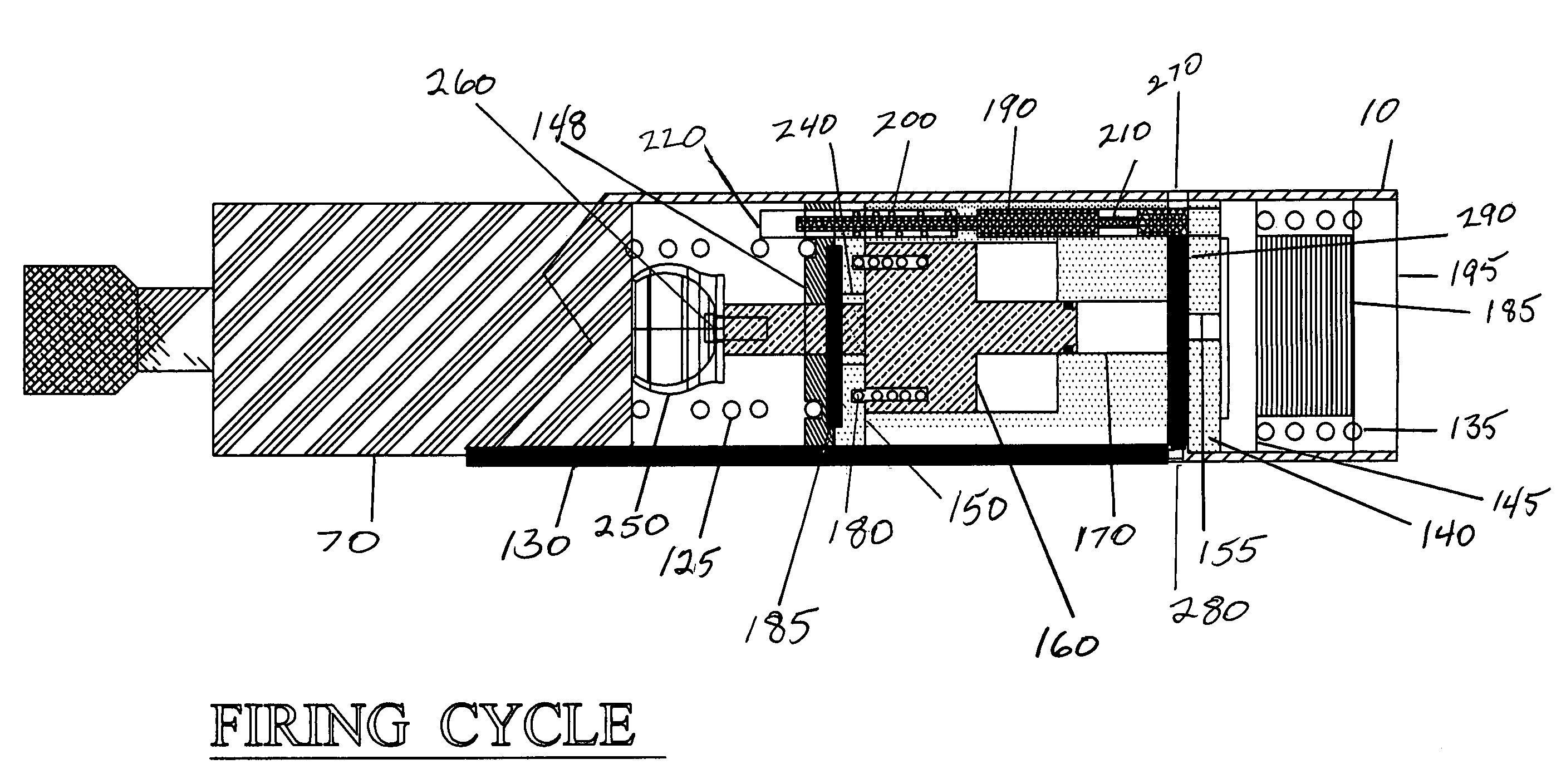
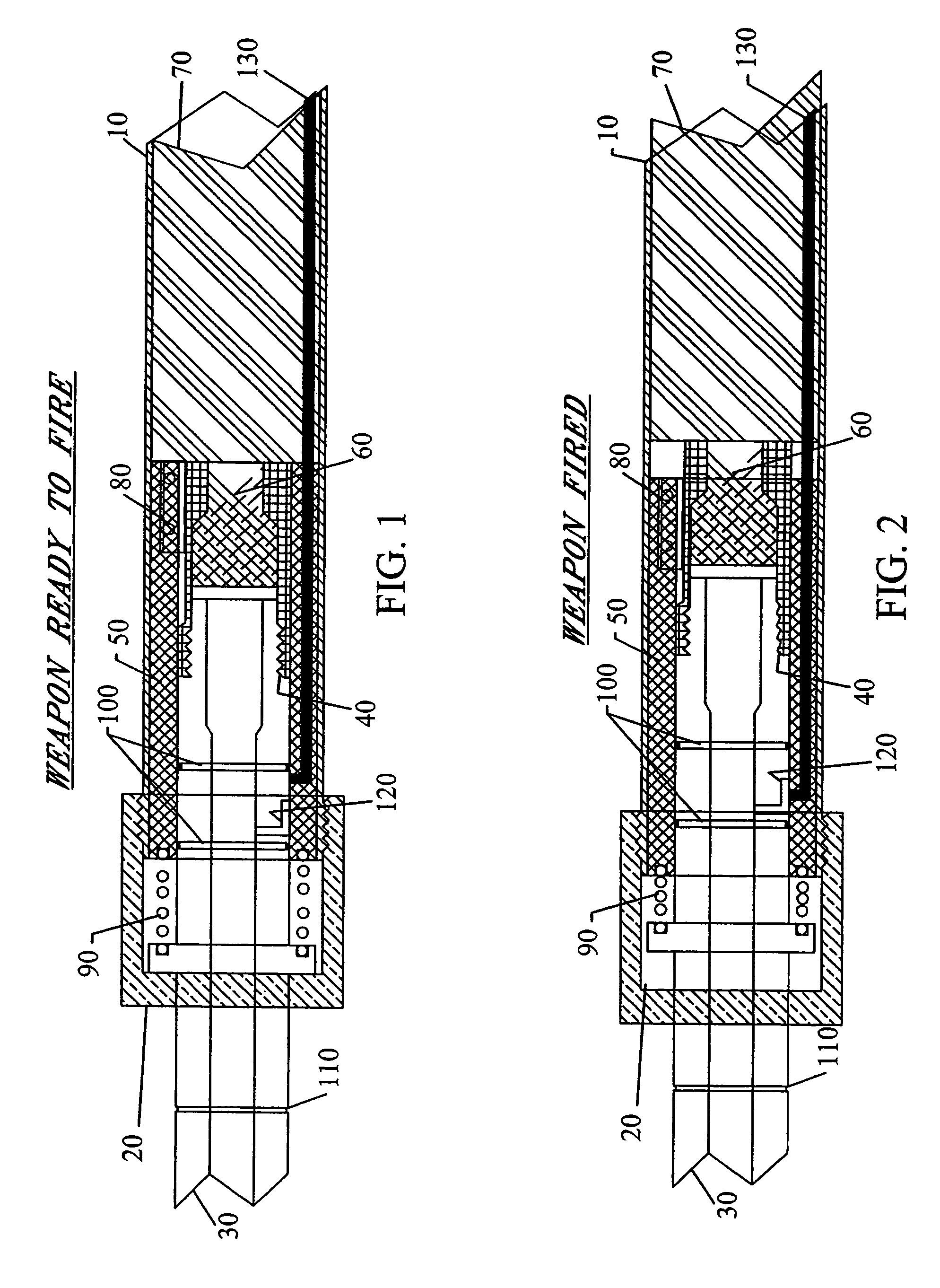
[0028]The present invention provides a recoil reducing system for a firearm or weapon that utilizes excess energy in the propelling gases to produce a counter or opposing force. The opposing force reduces recoil to a level that allows for reliable functioning of the weapon and a safe level of recoil for the weapon operator. In addition, the firing of the weapon will generate electrical power that eliminates the need for costly and heavy non-rechargeable (i.e. single use) batteries required for sighting, communications, and identification systems currently in use by military forces. The preferred embodiment is a short recoil operating system with a self-generating firing cycle that is readily adaptable to all known operating systems.

Barrel and Bolt Assembly

[0029]With reference initially to FIGS. 1-4, a firearm or weapon is preferably adapted with an anti-recoil system by modifications to the barrel and receiver sections as disclosed herein. The firearm includes a receiver outer housi...


PUM


Abstract

An anti-recoil system for counteracting recoil in firearms and weapons using a gas actuated piston assembly is disclosed. A recoil piston is acted upon by gas pressure routed from the receiver / barrel. High pressure gas causes forward movement of the recoil piston thereby generating a force opposing the recoil generated upon firing. A shock absorbing bumper connected to the piston engages the weapon's rearwardly moving bolt assembly. The bolt assembly forces the recoil piston rearward and compresses the bumper and expanded gas in the recoil piston chamber thereby absorbing additional recoil forces. Upon reaching a rear most position a gas relief valve is opened allowing venting of the compressed gases at which point the bolt operating main spring propels the bolt assembly forward, stripping the top round out of the ammunition magazine, loading the next round, locking the bolt and freeing the firing pin to fire the next round. An electrical generation system designed to meet the current and future needs for individual combatants utilizes hereto fore wasted energies produced in the firing of a modern weapon. Specifically it is designed to convert the wasted energy contained in the ejected high pressure gasses and the subsequent recoil produced by the gasses accelerating a projectile to high velocities, and the energy contained in the rapidly moving bolt assembly. This energy is capable of being stored within the weapon, or in external, individual battery packs.

Description

CROSS REFERENCE TO RELATED APPLICATIONS[0001]This application claims the benefit of provisional U.S. Patent Application Ser. No. 60 / 609,946 filed Sep. 15, 2004.STATEMENT REGARDING FEDERALLY SPONSORED RESEARCH OR DEVELOPMENT[0002]N / ACOPYRIGHT NOTICE[0003]A portion of the disclosure of this patent document contains material that is subject to copyright protection. The copyright owner has no objection to the facsimile reproduction by anyone of the patent document or patent disclosure as it appears in the Patent and Trademark Office patent file or records, but otherwise reserves all copyrights rights whatsoever.BACKGROUND OF THE INVENTION[0004]1. Field of the Invention[0005]The present invention relates to firearms, and more particularly, to a recoil reducing and electrical generation system for large caliber, shoulder-fired weapons.[0006]2. Description of Related Art[0007]Problems relating to recoil when a firearm is discharged have been present in the art for centuries. Recoil results...

Claims


Application Information

Patent Timeline
Patent Type & Authority Patents(United States)
IPC IPC(8): F41A3/94
CPCF41A3/94
Inventor POFF, JR., CHARLES
Owner POFF JR CHARLES
Learn More