Method, device and magnetic resonance tomography system for monitoring emitted RF energy

a technology of magnetic resonance tomography and emitted energy, which is applied in the direction of magnetic measurements, measurement devices, instruments, etc., can solve the problems of reduced transmission power, and limited function of radio frequency apparatus, so as to prevent radiated radio frequency power

Active Publication Date: 2008-03-11
SIEMENS HEALTHCARE GMBH
View PDF11 Cites 30 Cited by
  • Summary
  • Abstract
  • Description
  • Claims
  • Application Information

AI Technical Summary

Benefits of technology

[0012]An object of the present invention is to provide a method, device and magnetic resonance imaging apparatus for monitoring a radio frequency apparatus to safely prevent the radiated radio frequency power from exceeding a limit value that is dangerous for the patient, while allowing an optimally good approach to this safe limit value so that data acquisition can take place with optimally high transmission power below the limit value.
[0017]The inventive method in particular has the advantage that separate measurement values, that respectively represent the radio frequency pulses emitted via the appertaining transmission path, can be measured for each of the transmission paths in a radio frequency apparatus that emits radio frequency pulses via a number of transmission paths. Using the measurement values, separate exposure values then can be determined for each of the measurement paths. These separate exposure values represent the physiological effect that the radio frequency pulses emitted via the appertaining transmission path actually have on the subject exposed to the radio frequency pulses. The generation of the exposure-monitoring values must then be based on a suitable combination of the separate exposure values, for example a simple addition or weighted addition of the exposure values determined for the individual transmission paths. For example, in this method it is possible to evaluate the transmission paths differently (namely corresponding to the actual SAR exposure for that path or channel caused by the transmission power thereof) for each of the transmission paths (which RF energy is emitted respectively with different frequencies and / or via coils of different types, positions and geometries) in multinuclear spectroscopy scans (examination).
[0029]In an embodiment, monitoring of the exposure values (and thus the radio frequency power) ensues via various nested time windows, (for example) a short-term monitoring and a long-term monitoring are implemented. Respective exposure-monitoring values are simultaneously determined for a number of time windows of different lengths (preferably for two time windows of 10 s and 360 s) and compared with exposure limit values applicable for the respective time spans. The radio frequency apparatus is then limited in terms of function if only one of the exposure-monitoring values reaches or exceeds the associated exposure limit value. This method serves for monitoring the irradiation of a specific higher dose over a longer time window and simultaneously ensures that the entire power that is permissible within the long time window to be monitored is not radiated onto the patient within a short time window, which would be dangerous for the patient exists due to the short-term exposure elevation.

Problems solved by technology

The radio frequency apparatus is limited in function when an exposure-monitoring value reaches or exceeds an exposure limit value.
In the inventive method, a limitation of the functioning of the radio frequency apparatus can be, for example, a shutdown of the RF transmission device or the radio frequency power amplification device, or a temporary deactivation of one or both devices, or a reduction of the transmission power.

Method used


Image

  • Method, device and magnetic resonance tomography system for monitoring emitted RF energy
  • Method, device and magnetic resonance tomography system for monitoring emitted RF energy
  • Method, device and magnetic resonance tomography system for monitoring emitted RF energy

Examples


Embodiment Construction

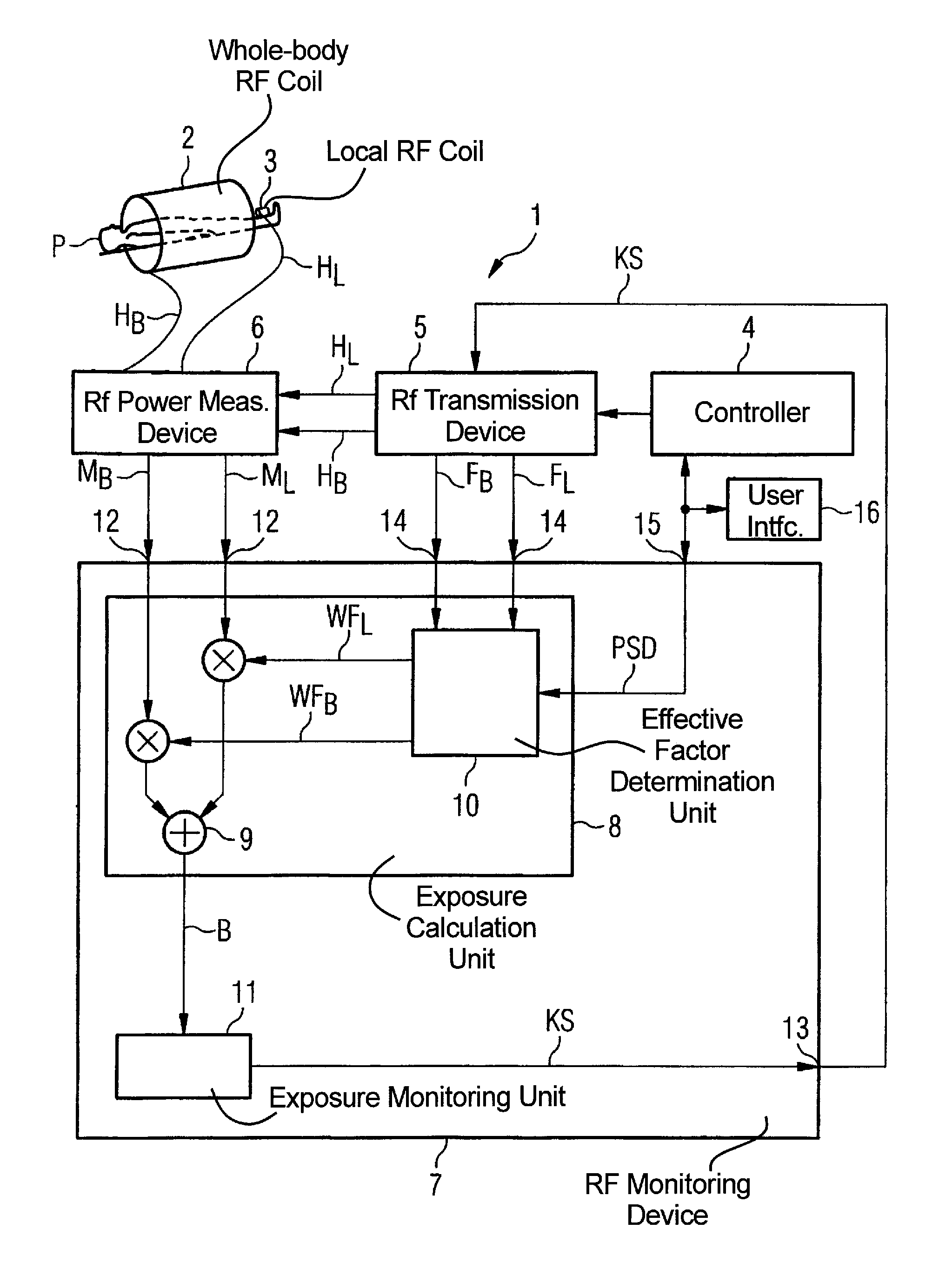
[0038]As a basic component of a magnetic resonance tomography system, FIG. 1 shows a radio frequency apparatus 1, the representation selected here concentrating on the transmission branch of the radio frequency apparatus.

[0039]In addition to the transmission branch of the radio frequency apparatus 1, the magnetic resonance tomography system has a magnetic resonance scanner including a magnet system (not shown) for generation of a measurement field that at least partially surrounds a patient P during an examination as well as gradient coils (likewise not shown) for application of magnetic field gradients. Moreover, a radio frequency reception system (not shown) is provided with at least one reception coil and a suitable reception amplifier. The radio frequency apparatus has transmission coils 2, 3, which can also form the aforementioned reception coils. An image computer (not shown) that reconstructs images from the acquired signals in a known manner, for display on a screen, and / or ...


PUM


Abstract

In a method, device and magnetic resonance tomography system for monitoring a radio-frequency apparatus in which radio-frequency pulses are emitted at temporal intervals and in which measurement values representing the power of the radio-frequency pulses are measured at temporal intervals, the measurement values are used to determine exposure values that represent a physiological effect that the radio-frequency pulses have on a subject exposed to the radio-frequency pulses. Based on a number of exposure values, exposure-monitoring values are respectively formed and the radio-frequency apparatus is limited in function if an exposure-monitoring value reaches or exceeds an exposure limit value.

Description

BACKGROUND OF THE INVENTION[0001]1. Field of the Invention[0002]The present invention concerns a method for monitoring RF energy emission by a radio frequency apparatus as well as a corresponding radio frequency apparatus and a corresponding radio frequency monitoring apparatus for implementation of such a method. Moreover, the invention concerns a magnetic resonance tomography system with such a radio frequency apparatus.[0003]2. Description of the Prior Art[0004]Magnetic resonance imaging, based on examination of the nuclear magnetic resonance of protons of a body region, has become established as an imaging modality in the medical field. In this modality, a strong, stable, homogenous magnetic field is initially generated around the body region, causing a stable alignment of the protons in the appertaining body region. This stable alignment is then altered by radio frequency energy emitted in to the body region. This energetic simulation is ended and the magnetic resonance signals...

Claims


Application Information

Patent Timeline
Patent Type & Authority Patents(United States)
IPC IPC(8): G01V3/00
CPCG01R33/288G01R33/543G01R33/3607
Inventor BIELMEIER, WOLFGANGLUDWIG, KLAUS
Owner SIEMENS HEALTHCARE GMBH
Why Eureka
Try Eureka