Calibration source for calibrating spectroradiometer, calibration method using the same, and calibration system
a calibration source and spectroradiometer technology, applied in the direction of optical radiation measurement, instruments, spectrometry/spectrophotometry/monochromators, etc., can solve the problem that it is substantially impossible for a user to re-calibrate or correct the spectral sensitivity of the spectroradiometer, and the return cost and time are required. , to achieve the effect of reducing the cost and time of the return, reducing the cost and tim
- Summary
- Abstract
- Description
- Claims
- Application Information
AI Technical Summary
Benefits of technology
Problems solved by technology
Method used
Image
Examples
first embodiment
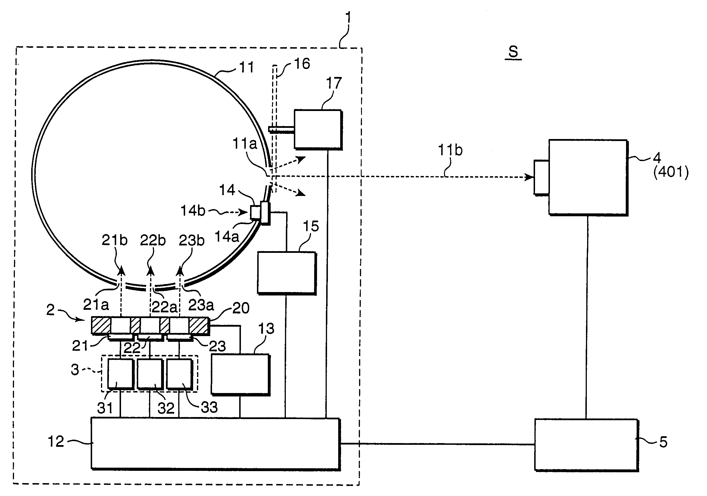
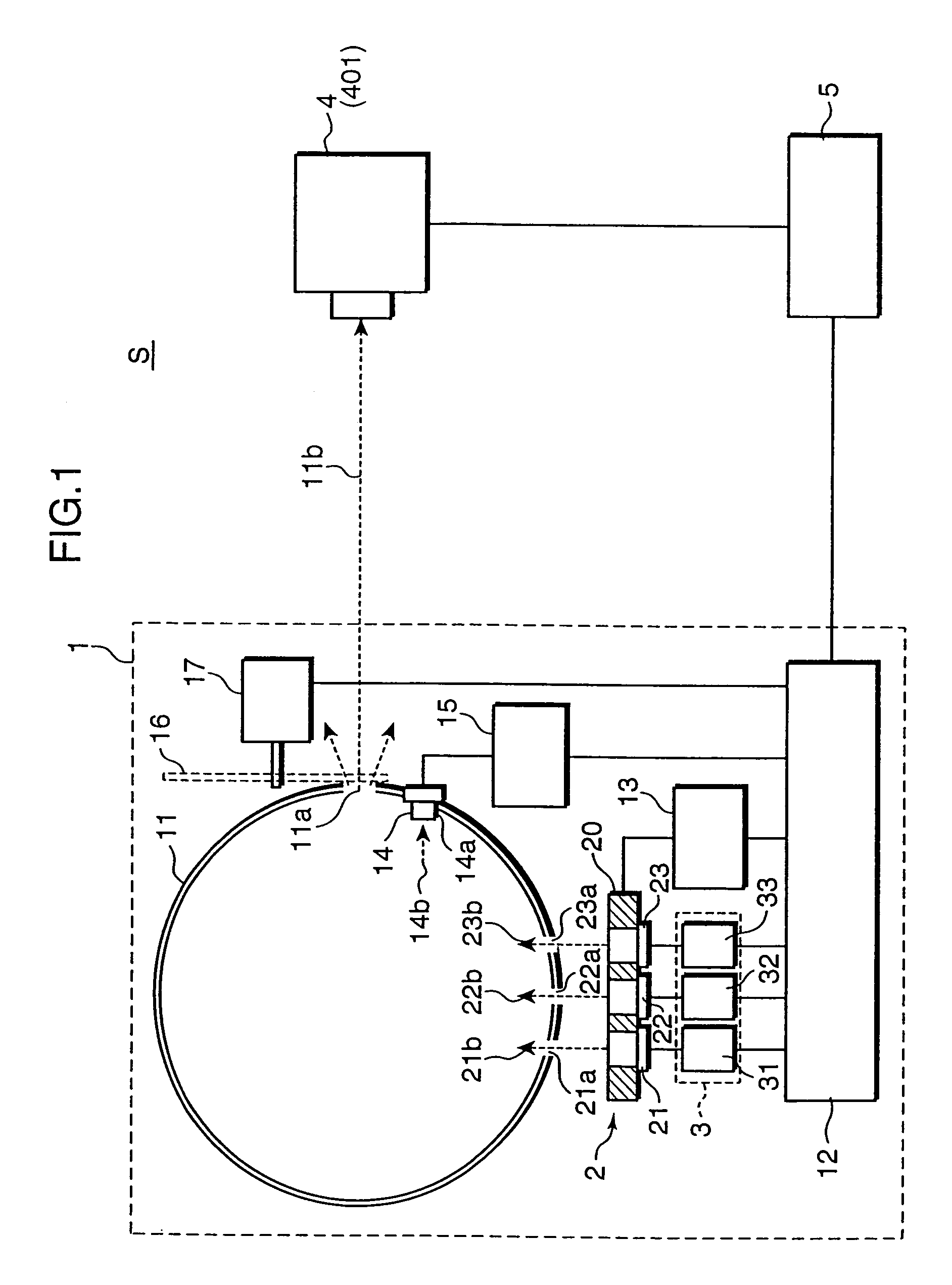
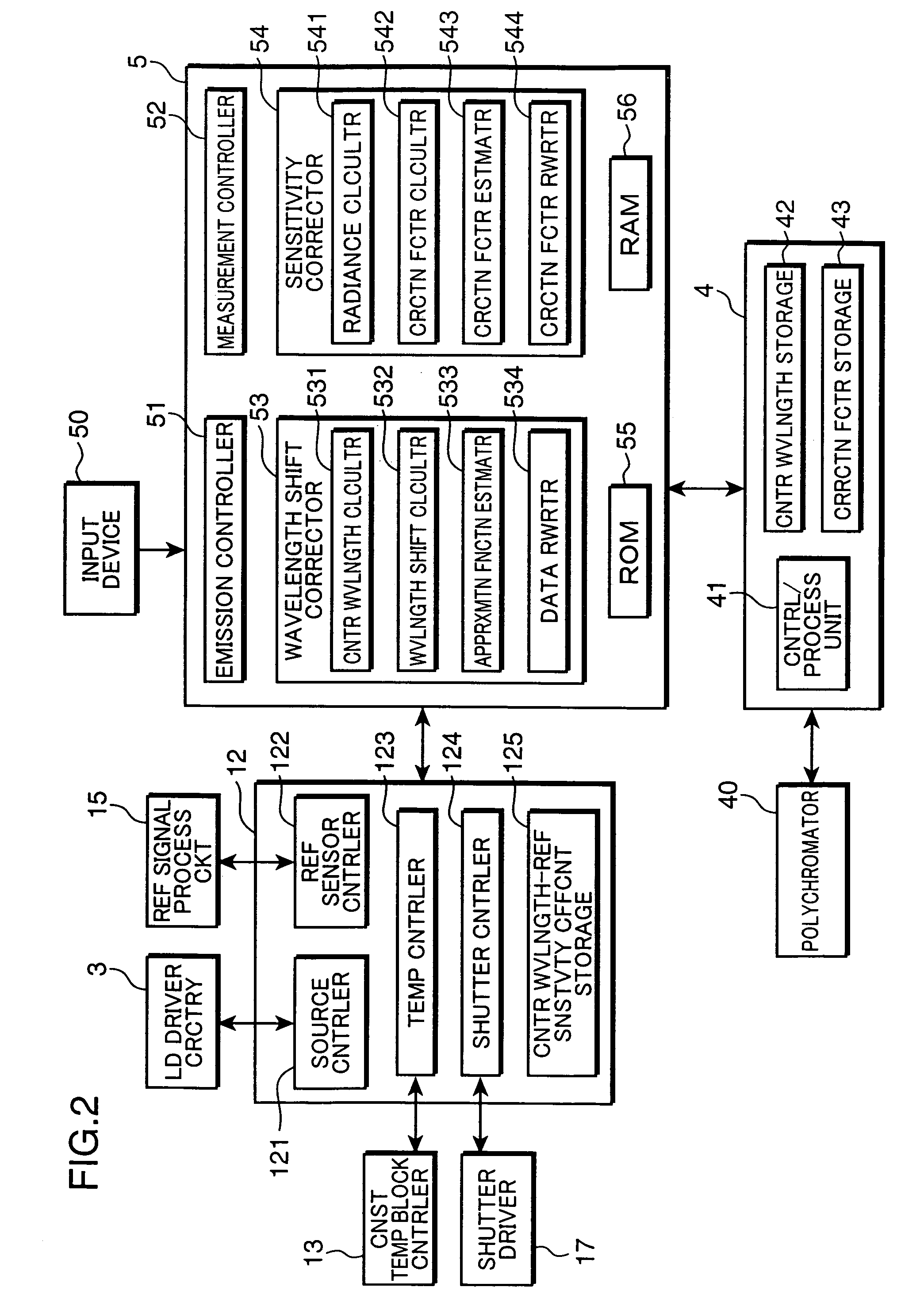
[0032]FIG. 1 is a system block diagram showing a construction of a calibration system S using a calibration source for calibrating a spectroradiometer in accordance with a first embodiment of the invention. FIG. 2 is a functional block diagram showing a functional arrangement of the calibration system S. The calibration system S includes a calibration source 1 for calibrating a spectroradiometer 4, the spectroradiometer 4 to be calibrated, and a personal computer 5 (hereinafter called as “control PC 5”) for controlling the calibration system S.
[0033]The calibration source 1 includes an integrating sphere 11, a control / processing unit 12, a reference sensor 14, a laser unit 2, a laser (LD) driver circuitry 3, and a shutter 16. The integrating sphere 11 has a highly reflective and highly diffusive inner wall, with three incident apertures 21a, 22a, and 23a, and one exit aperture 11a. The integrating sphere 11 is designed in such a manner that light incident through the incident apertu...
second embodiment
[0103]FIG. 10 is a system block diagram showing an arrangement of a calibration system Sa using a calibration source 1a of a spectroradiometer in accordance with a second embodiment of the invention. FIG. 11 is a functional block diagram showing a functional arrangement of the calibration system Sa. The calibration system Sa includes the calibration source 1a, a spectroradiometer 4 to be calibrated, and a control personal computer (PC) 5a. The basic arrangement of the second embodiment is substantially the same as that of the first embodiment, and elements in the second embodiment having the same reference numerals as in FIGS. 1 and 2 are the same elements or functional parts as in the first embodiment. In the following, description on the elements identical or equivalent to those in the first embodiment is omitted or simplified, and features of the second embodiment different from the first embodiment are primarily described.
[0104]As shown in FIG. 10, the second embodiment is subst...
third embodiment
[0129]FIG. 13 is a system block diagram showing an arrangement of a calibration system Sb of a spectroradiometer using a calibration source 1b in accordance with a third embodiment of the invention. The calibration system Sb includes the calibration source 1b, the spectroradiometer 4 to be calibrated, and a control personal computer (PC) 5b. The basic arrangement of the third embodiment is substantially the same as that of the first embodiment, and elements in the third embodiment having the same reference numerals as in FIG. 1 are the same elements or functional parts as in the first embodiment. In the following, description on the elements identical or equivalent to those in the first embodiment is omitted or simplified, and features of the third embodiment different from the first embodiment are primarily described.
[0130]The third embodiment is different from the first embodiment in that diffusers 21d, 22d, and 23d constitute individual calibration sources for monochromatic refer...
PUM
 Abstract
Description
Claims
Application Information
 - R&D
- Intellectual Property
- Life Sciences
- Materials
- Tech Scout
- Unparalleled Data Quality
- Higher Quality Content
- 60% Fewer Hallucinations
Browse by: Latest US Patents, China's latest patents, Technical Efficacy Thesaurus, Application Domain, Technology Topic, Popular Technical Reports.
© 2025 PatSnap. All rights reserved.Legal|Privacy policy|Modern Slavery Act Transparency Statement|Sitemap|About US| Contact US: help@patsnap.com


