
Device and method for controlling engine

a technology of engine control and control device, applied in the direction of electrical control, process and machine control, instruments, etc., can solve the problems of impairing driving comfort, increasing noise rapidly, and slowing down the change in combustion noise, so as to achieve the effect of preventing the rapid change of combustion noise and slowing down the change of combustion nois

Inactive Publication Date: 2008-03-04
TOYOTA JIDOSHA KK
View PDF11 Cites 9 Cited by
  • Summary
  • Abstract
  • Description
  • Claims
  • Application Information

AI Technical Summary

Benefits of technology

The solution effectively reduces rapid combustion noise changes during acceleration, enhancing driving comfort by smoothing the noise profile and optimizing fuel consumption without significantly impacting driving performance or increasing fuel consumption.

Problems solved by technology

In this case, combustion noise increases rapidly in a short time in an initial stage of the acceleration as surrounded by an ellipse in FIG. 10, which may impair driving comfort depending on the degree of the acceleration.
However, if the stop of the pilot injection is carried out concurrently in all cylinders, the combustion noise rapidly increases and this brings discomfort to a driver, thus impairing driving comfort.
With the technology described therein, however, since the pilot injection is performed uniformly across a predetermined speed-torque range, the rapid change of combustion noise at a rapid acceleration or the like still occurs, which may impair driving comfort depending on the degree of the acceleration.

Method used


Image

  • Device and method for controlling engine
  • Device and method for controlling engine
  • Device and method for controlling engine

Examples


Embodiment Construction

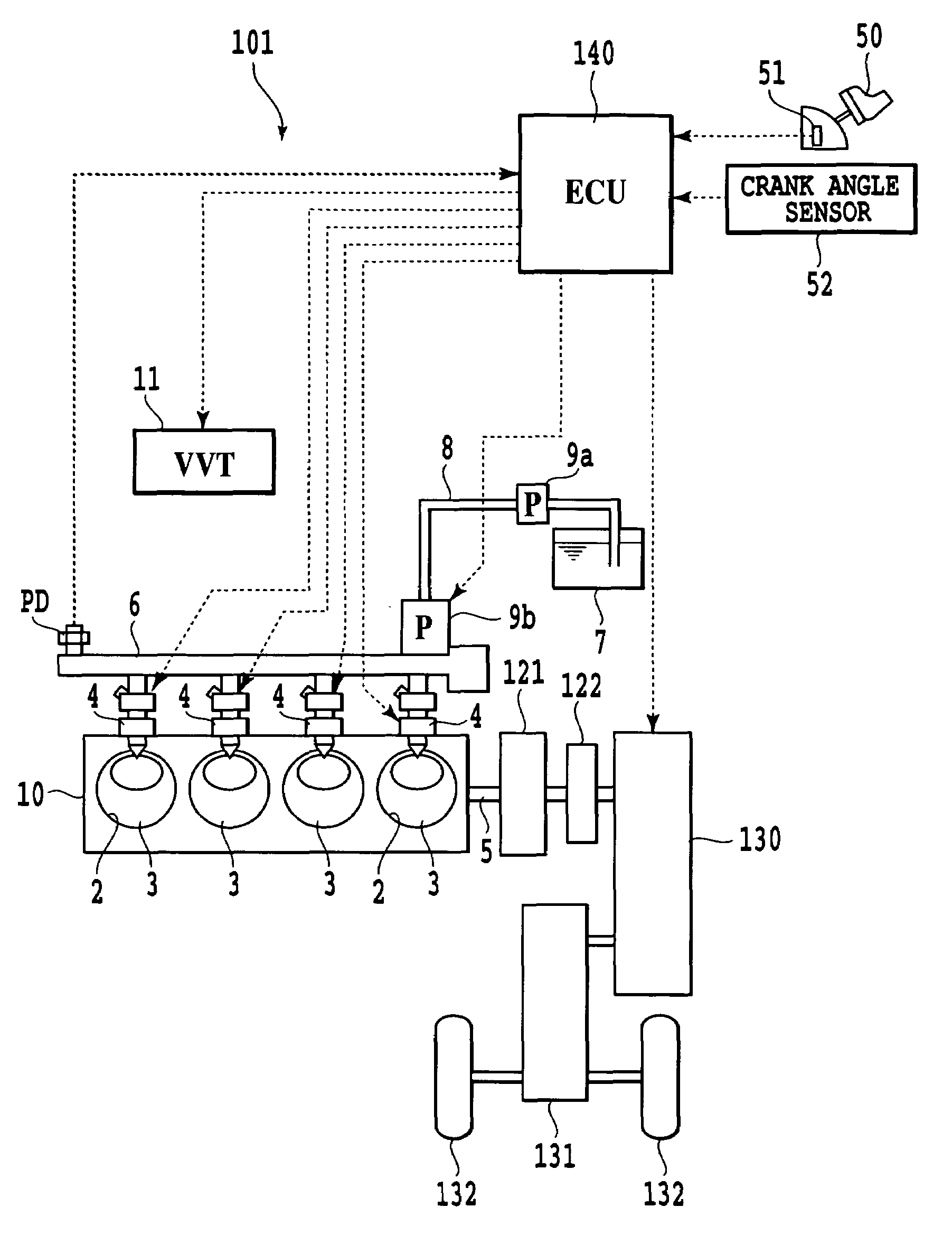
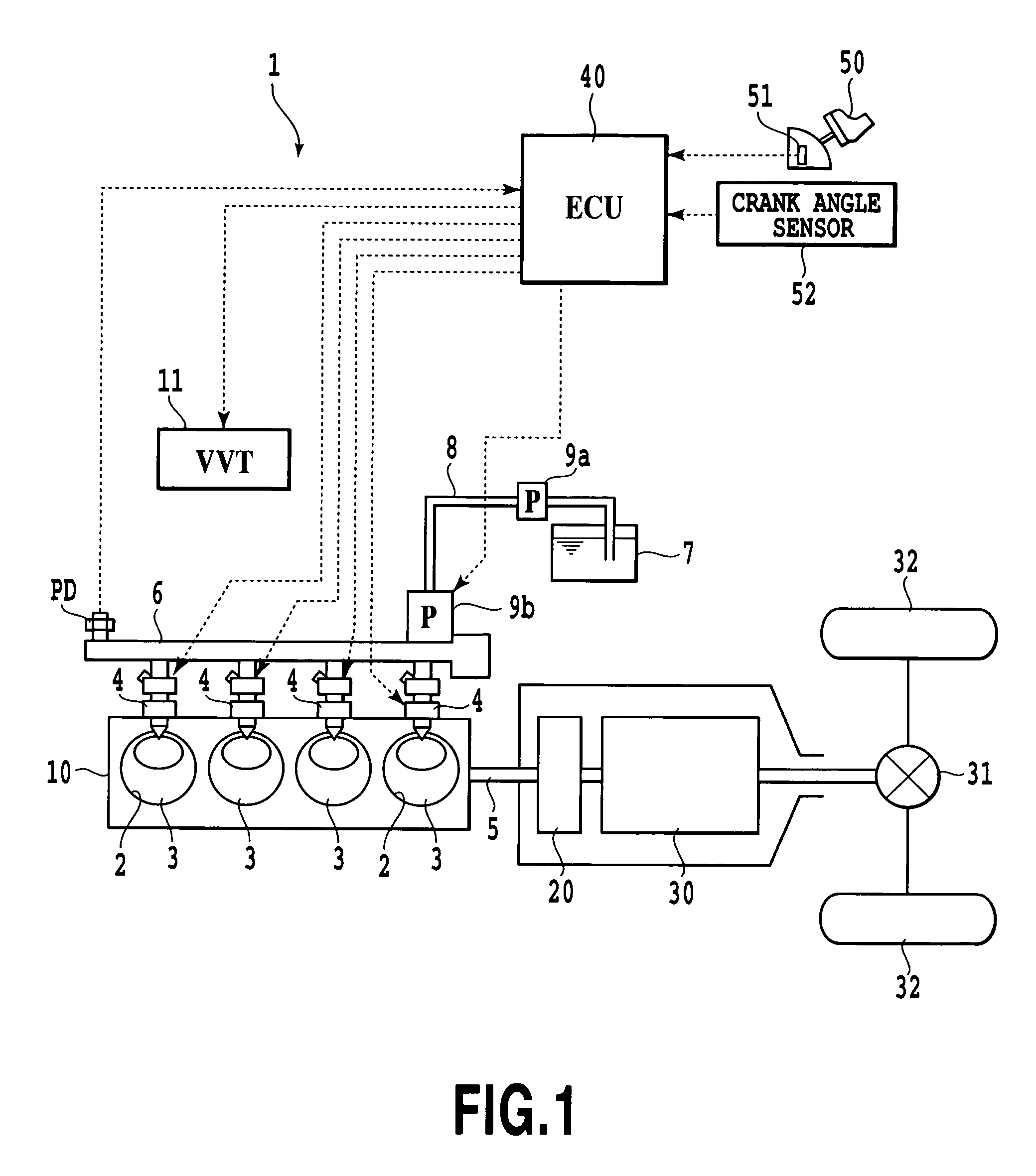
[0034]Preferred embodiments of the present invention will hereinafter be described. Referring to FIG. 1, a vehicle 1 according to a first preferred embodiment of the present invention is equipped with an engine 10, which is a cylinder direct injection internal combustion engine, such as a diesel engine or a gasoline engine. The engine 10 includes cylinders 2 formed inside a cylinder block, into which pistons 3 are slidably inserted. A combustion chamber is defined by the cylinders 2, the pistons 3, and a cylinder head block (not shown).

[0035]The pistons 3 are coupled to a crankshaft 5 by a connecting rod (not shown). Inside the cylinder head, an intake port and an exhaust port (not shown) are formed for each cylinder, in which an intake valve and an exhaust valve (not shown) are set respectively. A part of an intake passage upstream of the intake port is provided with a throttle valve or an intake throttle valve (not shown) controlled by a throttle actuator.

[0036]A fuel injection va...


PUM


Abstract

In a device for controlling an engine, comprising combustion noise suppressor for suppressing combustion noise of a combustion chamber and controller for controlling the combustion noise suppressor, the device further includes control amount setter for setting a control amount of the combustion noise suppressor so that target combustion noise characteristics corresponding to a required amount of acceleration or deceleration exhibit a slower change in combustion noise than combustion noise characteristics corresponding to output characteristics of the engine over before and after acceleration or deceleration, wherein the controller controls the combustion noise suppressor according to the control amount set by the control amount setter. On the event of a rapid acceleration, a rapid change in the combustion noise in the initial stage of the acceleration is prevented to improve driving comfort.

Description

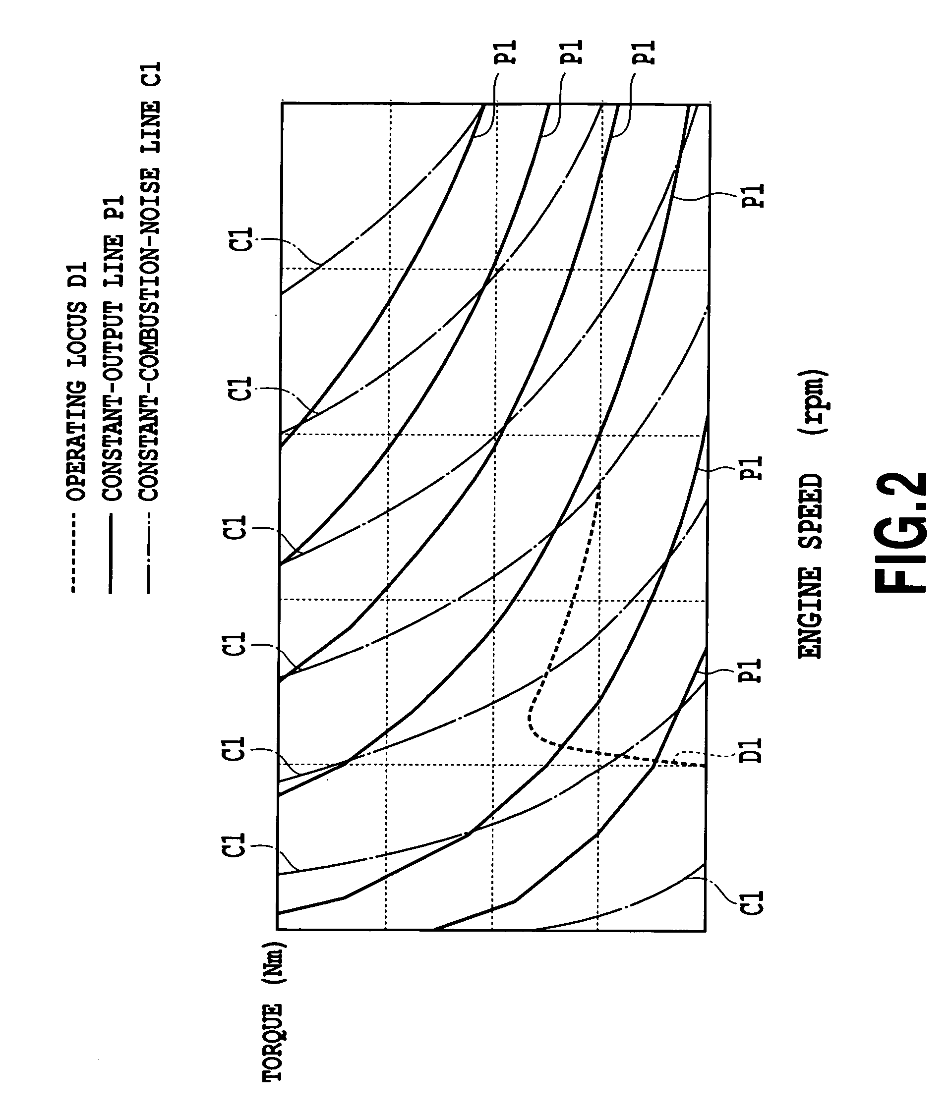
TECHNICAL FIELD[0001]The present invention relates to a device and method for controlling an engine, and particularly to one adapted to prevent a rapid change in combustion noise.BACKGROUND ART[0002]Combustion noise characteristics of an engine are said to generally correspond to an output, which is a product of torque and speed. That is to say, as shown in FIG. 9, output contours and combustion noise contours of an engine on a speed-torque plane, i.e., constant-output lines Pp and constant-combustion-noise lines Cp correspond to each other within a predetermined range, i.e., virtually overlap with each other with a generally common peak point existing at central sides of the approximately arc-shaped constant-output lines Pp and constant-combustion-noise lines Cp, thus providing substantially similar characteristics.[0003]On the other hand, in a vehicle equipped for example with manual transmission means, an operating locus Dp when an accelerator pedal is depressed without any gear ...

Claims


Application Information

Patent Timeline
Patent Type & Authority Patents(United States)
IPC IPC(8): F02D41/38F02D41/40F02D45/00F02D29/00F02D41/04F02D41/10
CPCF02D41/10F02D41/403Y02T10/44F02D2200/025Y02T10/40
Inventor MAGARIDA, NAOFUMIISHIYAMA, SHINOBU
Owner TOYOTA JIDOSHA KK
Learn More