Method for improving depth discrimination in optical reproduction systems

a technology of optical reproduction and depth discrimination, applied in the direction of projectors, instruments, material analysis, etc., can solve the problems of inability to maintain the necessary constancy of individual phase displacement steps in practice, the physical boundary conditions required for the application of the indicated method are very difficult to achieve in practice, and the stripe artifacts in the generated section images cannot be realized. , to achieve the effect of improving the depth discrimination of optical imaging systems

Active Publication Date: 2008-02-26
CARL ZEISS MICROSCOPY GMBH
View PDF11 Cites 13 Cited by
  • Summary
  • Abstract
  • Description
  • Claims
  • Application Information

AI Technical Summary

Problems solved by technology

A problem arising in conventional light microscopy when examining three-dimensionally extending objects, i.e., objects whose extension along the optical axis is greater than the depth of focus of the objectives that are used, consists in that the in-focus image from the region of focus is superposed with extra-focal image components which are accordingly imaged out of focus.
Realizing the physical boundary conditions required for the application of the indicated method proves very difficult in practice.
For example, variation in lamp brightness between the different recordings leads to stripe artifacts in the generated section images.
With fluorescing objects, additional problems occur due to the time-dependent fading of the fluorescent dyes, which likewise results in errors.
The necessary constancy of the individual phase displacement steps cannot be maintained in practice.
A considerable expenditure on instrumentation is required in order to realize these suggestions.
Further, the recording of additional images prolongs the required recording time and therefore also increases aging of the sample by illumination with the fluorescence excitation light.

Method used


Image

  • Method for improving depth discrimination in optical reproduction systems
  • Method for improving depth discrimination in optical reproduction systems
  • Method for improving depth discrimination in optical reproduction systems

Examples


Embodiment Construction

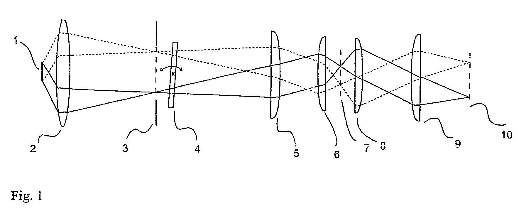
[0021]FIG. 1 is a simplified optical schematic illustrating the structured illumination with transmitted illumination by way of example. The imaging beam path (image-forming beam path) is shown. A one-dimensional periodic structure (transmission grating) (3) which is located in a conjugated object plane of the optical arrangement shown in the drawing is illuminated by a light source (1) through collector optics (2). The grating is followed in light direction by a plane-parallel glass plate (4). The angle of the plane-parallel plate relative to the optical axis can be adjusted in a defined manner. The structure is imaged in the specimen plane (7) by the illumination-side optics (5, 6) (condenser). Imaging is effected by the light coming from the specimen through a pair of lenses (8, 9) (objective and tube lens) in the image plane (10) following the latter in which, e.g., a CCD matrix of a digital camera can be arranged. By tilting it in a defined manner, the plane-parallel glass plat...


PUM


Abstract

The invention is directed to a method for improving the depth discrimination in optically imaging systems. It is applicable in particular in light microscopy for improving image quality when examining three-dimensionally extending objects. It is applicable in the method of structured illumination as described in WO 97 / 6509. For this purpose, influences due to variations in the brightness of the light source, positioning of the imaged periodic structure and bleaching of the object in fluorescence illumination are determined and taken into account in the calculation of the object structure.

Description

CROSS-REFERENCE TO RELATED APPLICATIONS[0001]This application claims priority of International Application No. PCT / EP2003 / 11927, filed Oct. 28, 2003 and German Application No. 102 50 568.3, filed Oct. 28, 2002, the complete disclosures of which are hereby incorporated by reference.BACKGROUND OF THE INVENTION[0002]a) Field of the Invention[0003]The invention is directed to a method for depth discrimination in optically imaging systems. In particular, it is applicable in light microscopy for achieving an improvement in image quality in the examination of three-dimensionally extending objects.[0004]b) Description of the Related Art[0005]A problem arising in conventional light microscopy when examining three-dimensionally extending objects, i.e., objects whose extension along the optical axis is greater than the depth of focus of the objectives that are used, consists in that the in-focus image from the region of focus is superposed with extra-focal image components which are accordingl...

Claims


Application Information

Patent Timeline
Patent Type & Authority Patents(United States)
IPC IPC(8): G02B27/40G03B21/26G02B21/00G02B21/36
CPCG02B21/0004G02B21/361
Inventor BACKS, BERNHARDSCHAFFER, JOERGSCHAEFER, LUTZVOELCKER, MARTIN
Owner CARL ZEISS MICROSCOPY GMBH
Why Eureka
Try Eureka