
Method for scheduling upstream communications

a technology for upstream communication and transmission, applied in the field of controlling network transmission, can solve the problems of packet latency, packet loss or corruption, and the inability of cable modems to use the bandwidth granted, and achieve the effect of higher priority

Inactive Publication Date: 2008-02-19
AVAGO TECH INT SALES PTE LTD
View PDF33 Cites 80 Cited by
  • Summary
  • Abstract
  • Description
  • Claims
  • Application Information

AI Technical Summary

Benefits of technology

The present invention is a system and method for managing bandwidth allocation among multiple services operating over a widely distributed network. It uses a headend communications device to grant bandwidth to individual cable modems or groups of cable modems. Each cable modem has a local scheduler that selects packets to be transmitted based on local policies or rules. The system also allows for independent piggybacking to request additional bandwidth. The technical effects of this invention include efficient bandwidth allocation, improved service performance, and improved user experience.

Problems solved by technology

Problems arise when the service specified in the MAP is later determined to no longer require the bandwidth, or require more bandwidth than originally requested.
Another problem can occur if another service of equal or higher priority should require immediate bandwidth shortly after the headend's granting a lower-priority service's request bandwidth.
The cable modem may not be able to use the granted bandwidth to transmit data from the higher priority service, because the grant would be restricted to the lower priority service.
Transmitting a signal during a contention mode increases the likelihood of the packets colliding, getting loss or becoming corrupted.
Otherwise, piggybacking requests can add excessive packet overhead that require more bandwidth or may cause packet latency.

Method used


Image

  • Method for scheduling upstream communications
  • Method for scheduling upstream communications
  • Method for scheduling upstream communications

Examples


Embodiment Construction

Table of Contents

[0030]I. Data Traffic Management System Overview[0031]II. Cable Modem Scheduling[0032]III. Piggybacking Bandwidth Requests[0033]IV. Conclusion

I. Data Traffic Management System Overview

[0034]FIG. 1 illustrates data traffic management system 100 according to an embodiment of the present invention. System 100 is preferably, but not necessarily, of the type described in U.S. Patent Ser. No. 60,247,188, entitled “A Local Scheduling Mechanism for Cable Modems,” filed Nov. 9, 2000, by Sala et al., (still pending), which is incorporated by reference herein in its entirety.

[0035]System 100 includes a headend or cable modem termination system (CMTS) 102 that exchanges data with one or more cable modems 104 over a communications interface 110, which includes wired or wireless local area networks (LAN) or wide area networks (WAN), such as an organization's intranet, local internets, the global-based Internet (including the World Wide Web (WWW), private enterprise networks, or t...


PUM


Abstract

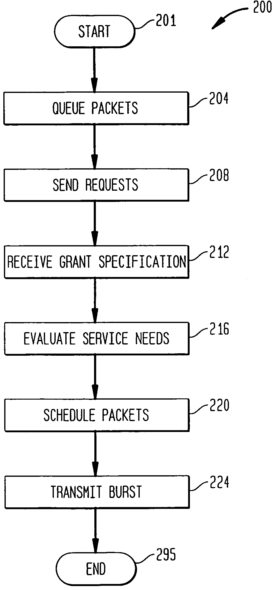
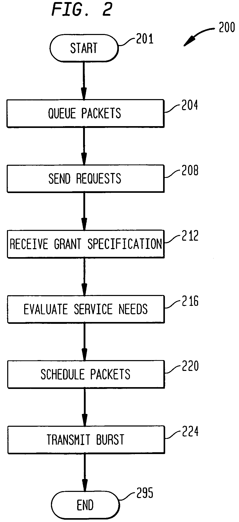
A system and method is provided for scheduling transmissions from a plurality of services operating over a widely distributed communications network. A headend communications device (such as a cable modem termination system) arbitrates bandwidth among a plurality of cable modems configurable for bi-directional communications. The headend grants a bandwidth region to a specified cable modem or assigns contention regions for a group of cable modems. Each cable modem contains a local scheduler that sends requests for bandwidth according to local policies or rules. Upon receipt of a grant from the headend, the local scheduler selects packets to be transmitted to best serve the needs of the services associated with the cable modem. Accordingly, a service requesting bandwidth may not be the service utilizing the grant corresponding to bandwidth request. Nonetheless, the local scheduler manages bandwidth allocation among its local services such that all requesting services eventually receive bandwidth.

Description

CROSS-REFERENCE TO RELATED APPLICATIONS[0001]This application is a continuation-in-part of U.S. patent application Ser. No. 09 / 427,792, entitled “System and Method for Multiplexing Data from Multiple Sources,” filed Oct. 27, 1999, by Limb et al., (still pending), which is incorporated by reference herein in its entirety. This application claims the benefit of the following United States provisional applications:[0002]U.S. Patent Application No. 60 / 182,470, entitled “Intelligent Silence Suppression,” filed Feb. 15, 2000, by Gummalla et al., (abandoned), which is incorporated by reference herein in its entirety;[0003]U.S. Patent Application No. 60 / 247,188, entitled “A Local Scheduling Mechanism for Cable Modems,” filed Nov. 9, 2000, by Sala et al., (abandoned), which is incorporated by reference herein in its entirety;[0004]U.S. Patent Application No. 60 / 254,415, entitled “A Local Scheduling Mechanism for Cable Modems,” filed Dec. 8, 2000, by Sala et al. (abandoned), which is incorpor...

Claims


Application Information

Patent Timeline
Patent Type & Authority Patents(United States)
IPC IPC(8): H04L12/56H04L12/24H04L12/28H04L12/64H04L29/06H04M7/00H04N7/173
CPCH04L12/2801H04L12/5693H04L12/5695H04L12/6418H04L29/06H04L29/06027H04L41/5022H04L47/15H04L47/2416H04L47/2433H04L47/245H04L47/35H04L47/60H04L47/6215H04L65/80H04M7/006H04N7/17309H04N21/2385H04N21/42676H04N21/437H04N21/44209H04N21/6118H04N21/6168H04N21/6377H04L41/0896H04L41/5087H04L41/509H04L41/5093H04L2012/6481H04L2012/6494H04L47/50H04L47/70H04L9/40H04L65/1101
Inventor SALA, DOLORSGUMMALLA, AJAY CHANDRA V.LIMB, JOHN O.PROTUS, RICHARD
Owner AVAGO TECH INT SALES PTE LTD
Learn More