
Lithographic apparatus and device manufacturing method

a technology of lithographic apparatus and manufacturing method, which is applied in the direction of photomechanical apparatus, instruments, optics, etc., can solve the problems of large data error risk, complex and expensive data handling and image driver systems, etc., and achieve the effect of greatly reducing the amount of data transferred (i.e., the requirement for image data) to the array

Active Publication Date: 2008-02-19
ASML NETHERLANDS BV
View PDF23 Cites 5 Cited by
  • Summary
  • Abstract
  • Description
  • Claims
  • Application Information

AI Technical Summary

Benefits of technology

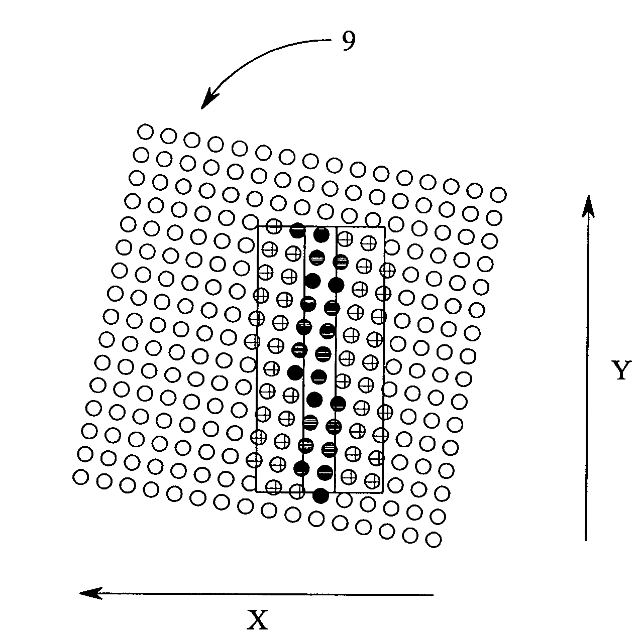
The present invention provides a method for manufacturing a device that can pattern a beam of radiation onto a target portion of a substrate. The method involves individually controlling elements of a beam of radiation to set the state of each element for the pattern. Only those elements that need to change state to create the pattern are addressed in each frame of the image. By addressing only the necessary elements, the data transfer requirement is significantly reduced, resulting in a faster data transfer rate or a reduction in the required data transfer rate. The method can be used in pixel grid imaging methods and can minimize aging of the device by reducing the number of changes of state of the individual elements.

Problems solved by technology

This can require the use of complex and expensive data handling and image driver systems.
In addition, with such high data transfer rates, the chance of data errors occurring can be relatively high.

Method used


Image

  • Lithographic apparatus and device manufacturing method
  • Lithographic apparatus and device manufacturing method
  • Lithographic apparatus and device manufacturing method

Examples


Embodiment Construction

Overview and Terminology

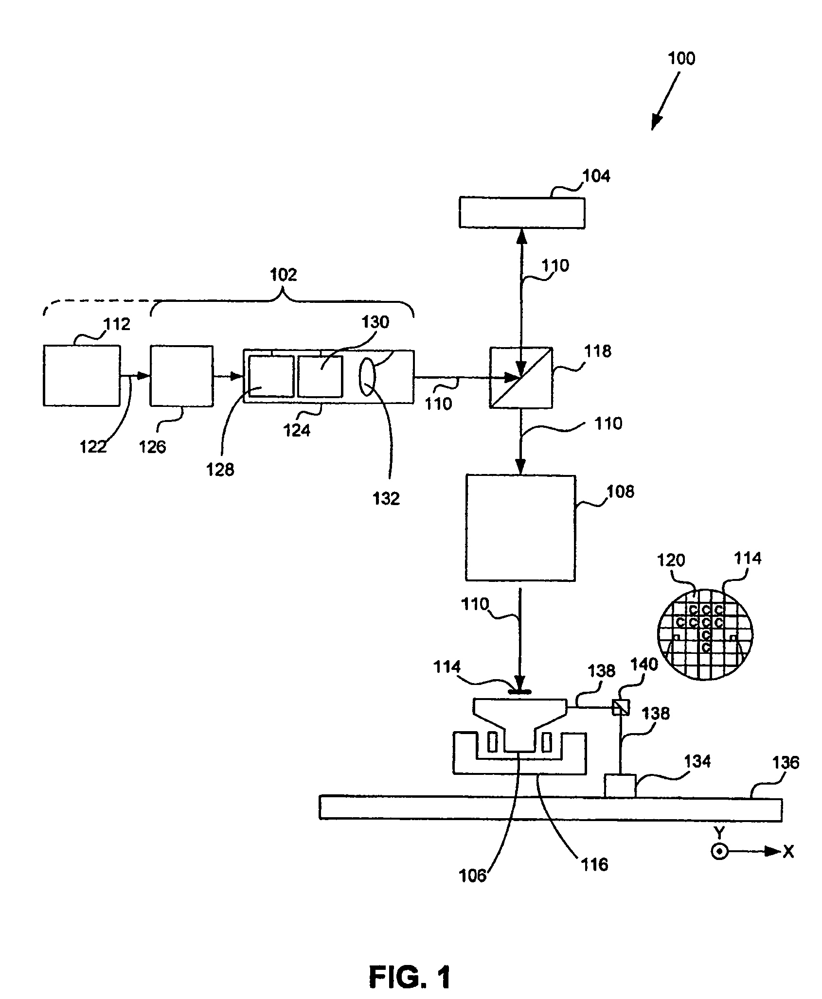
[0051]Although specific reference can be made in this text to the use of lithographic apparatus in the manufacture of integrated circuits (ICs), it should be understood that the lithographic apparatus described herein can have other applications, such as the manufacture of integrated optical systems, guidance and detection patterns for magnetic domain memories, flat panel displays, thin-film magnetic heads, micro and macro fluidic devices, etc. The skilled artisan will appreciate that, in the context of such alternative applications, any use of the terms “wafer” or “die” herein can be considered as synonymous with the more general terms “substrate” or “target portion,” respectively. The substrate referred to herein can be processed, before or after exposure, in for example a track (e.g., a tool that typically applies a layer of resist to a substrate and develops the exposed resist) or a metrology or inspection tool. Where applicable, the disclosure herein can...


PUM


Abstract

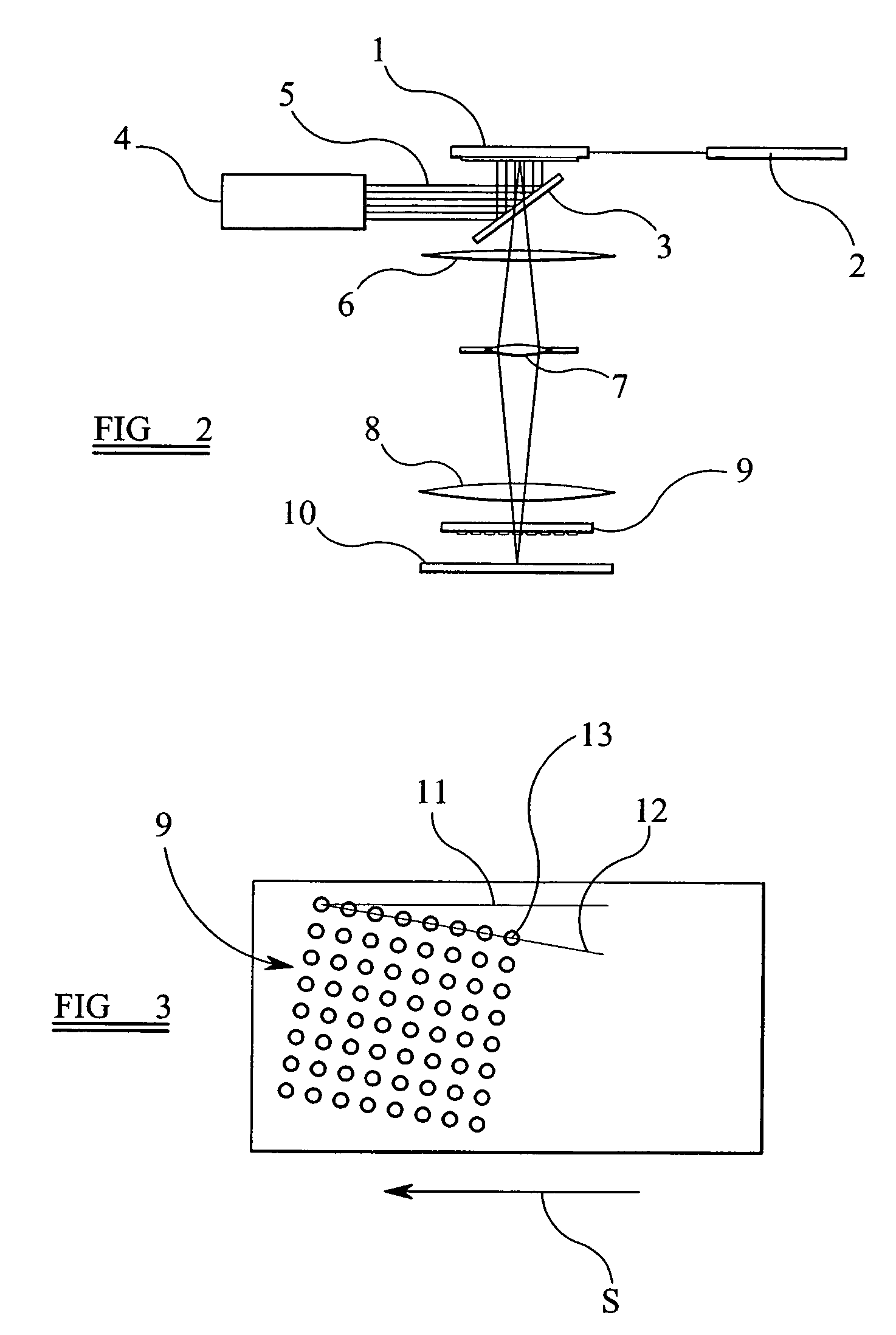
A lithographic method and apparatus used to pattern an object. An illumination system supplies a beam of radiation. An array of individually controllable elements patterns the beam. The patterned beam is projected by a projection system on to a substrate supported on a substrate table. Individual elements of the array are periodically addressed to load an image frame on to the array appropriate to the pattern to be imparted to the beam at any given instant in time taking into account the image to be projected onto the substrate. In any given frame loading operation, only those individual controllable elements that must change state are addressed to reduce the amount of data required to be transferred during the frame loading operation.

Description

BACKGROUND[0001]1. Field of the Invention[0002]The present invention relates to a lithographic apparatus and a device manufacturing method.[0003]2. Related Art[0004]A lithographic apparatus is a machine that applies a desired pattern onto a target portion of a substrate. The lithographic apparatus can be used, for example, in the manufacture of integrated circuits (ICs), flat panel displays, and other devices involving fine structures. In a conventional lithographic apparatus, a patterning means, that is alternatively referred to as a mask or a reticle, can be used to generate a circuit pattern corresponding to an individual layer of the IC (or other device), and this pattern can be imaged onto a target portion (e.g., comprising part of one or several dies) on a substrate (e.g., a silicon wafer or glass plate) that has a layer of radiation sensitive material (e.g., resist). Instead of a mask, the patterning means can comprise an array of individually controllable elements that gener...

Claims


Application Information

Patent Timeline
Patent Type & Authority Patents(United States)
IPC IPC(8): G03B27/54G02B26/00G03B27/42
CPCG03F7/70291G03F7/70508
Inventor GUI, CHENG-QUN
Owner ASML NETHERLANDS BV
Learn More