
Corrected image generating apparatus and corrected image generating program storage medium

a technology of image generating apparatus and program storage medium, which is applied in the direction of instruments, television systems, optical elements, etc., can solve the problems of inability to bear long-time monitoring, inability to correct deflection, and limited types of infrared ray cameras of airplanes or helicopters, so as to protect the continuity of an image, improve the accuracy, and improve the effect of accuracy

Inactive Publication Date: 2008-02-19
FUJITSU LTD
View PDF10 Cites 23 Cited by
  • Summary
  • Abstract
  • Description
  • Claims
  • Application Information

AI Technical Summary

Benefits of technology

[0012]When obtaining the feature point, it is necessary to carry out the pattern matching processing on an entire face of the raw image and it takes a quite long computation time. Thus, by generating a culling image to obtain the feature point on the culling image, the computation time can be reduced.
[0013]Because the motion vector is obtained by carrying out the pattern matching processing again about the raw image prior to the culling, its accuracy is not lowered. Further, because the motion vector only has to be obtained about the feature point, the computation can be finished in a short time.
[0017]When it is considered that the ground is photographed from an airplane or helicopter on which a camera is mounted, there may be an object which has a different deflection from that due to the vibration of the airplane or helicopter, such as a vehicle moving on the ground for example. Then, by employing the most frequent value vector having the highest frequency in motion vectors of typically plural feature points as the motion vector of that short strip, the high accuracy correction is enabled by avoiding a drop of the correction accuracy due to existence of an object having a different deflection from that due to the vibration of an airplane or helicopter.
[0019]Considering a case of photographing the ground by mounting a camera on an airplane or helicopter, the photographing range is moved slowly accompanied by flight of that airplane or helicopter. Of the motion vector, a component accompanied by this motion is not related to this vibration. Then, by carrying out a processing including the filtering processing over plural frames as described above, components accompanied by slow moving of the photographing range can be removed so that the motion vector originated from the vibration of the camera can be extracted at a high accuracy, thereby enabling a higher accuracy correction.
[0020]Further, in the corrected image generating apparatus of the present invention, when a method of carrying out the correcting each short strip is employed, preferably, the image correcting portion obtains a corrected image in which deflection between adjacent short strips in the arrangement direction is eliminated by shifting pixels arranged in the scanning direction in a short strip in the said arrangement direction.
[0021]Consequently, it is possible to protect continuity of an image from being lost at a joint between the short strips thereby making it possible to generate a natural corrected image having continuity.

Problems solved by technology

This deflection cannot be corrected according to a deflection correction method for the two-dimensional image obtained from such an ordinary camera.
However, when such a damper mechanism is mounted, the apparatus is enlarged and therefore, an airplane or helicopter capable of being provided with this infrared ray camera is limited to specific types.
When such photographing is carried out on an airplane or helicopter incapable of being provided with the damper mechanism, a monitor person gets tired of monitoring due to a deflection of images so that he cannot bear long-time monitoring.

Method used


Image

  • Corrected image generating apparatus and corrected image generating program storage medium
  • Corrected image generating apparatus and corrected image generating program storage medium
  • Corrected image generating apparatus and corrected image generating program storage medium

Examples


Embodiment Construction

[0044]Hereinafter, the preferred embodiments of the present invention will be described.

[0045]FIG. 1 is a schematic view of a photographing system including an embodiment of the corrected image generating apparatus of the present invention.

[0046]This photographing system 10 is a photographing system which is mounted on an airplane 1 for photographing the ground.

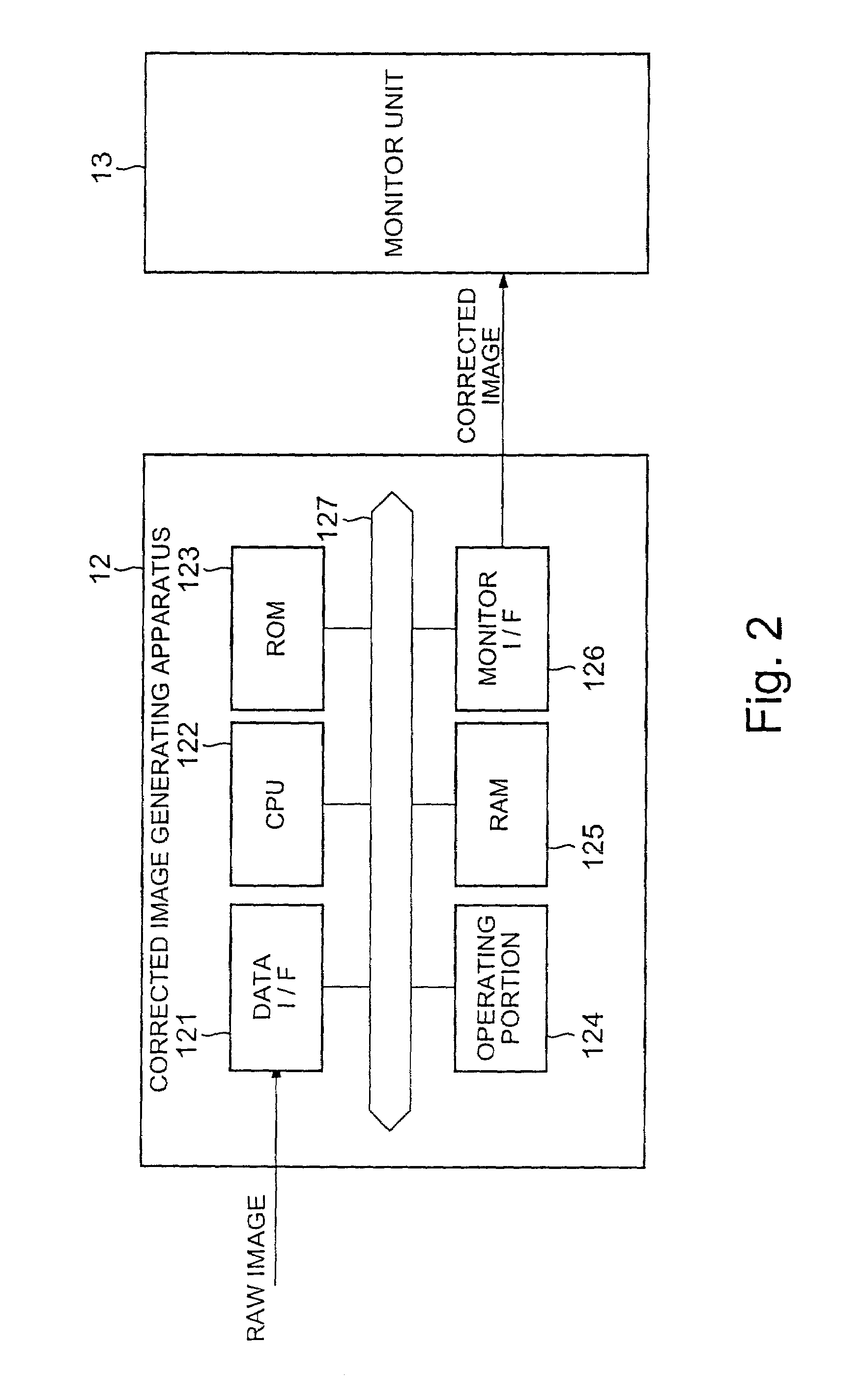
[0047]This photographing system 10 comprises an infrared ray camera 11, a corrected image generating apparatus 12, which is an embodiment of the present invention and a monitor unit 13 for displaying an image.

[0048]The infrared ray camera 11 has a one-dimensional image pickup device 111 in which a plurality of infrared ray receiving sensors are disposed one-dimensionally in a predetermined arrangement direction. By rotating a rotary polygon mirror 112, an image of a target 20 on the ground is scanned repeatedly over the one-dimensional image pickup device 111 so as to photograph images of plural frames. The image taken by thi...


PUM


Abstract

This invention provides a corrected image generating apparatus and the like for generating a corrected image by correcting a deflection due to the vibration of a camera in a raw image obtained by the camera which obtains the raw images of plural frames successively by scanning an object field of vision repeatedly in a scanning direction intersecting the arrangement direction of plural light receiving sensors composing the one-dimensional image pickup device in which the plural light receiving sensors are arranged one-dimensionally, in order to generate an image whose deflection is corrected. By obtaining a motion vector of each of short strips extending in the arrangement direction of the light receiving sensors of the one-dimensional image pickup device, the respective short strips are moved to obtain a corrected image.

Description

BACKGROUND OF THE INVENTION[0001]1. Field of the Invention[0002]The present invention relates to a corrected image generating apparatus for generating a corrected image by correcting a deflection due to vibration of a camera in a raw image obtained from the camera which obtains plural frames of raw images by scanning an object field of vision repeatedly using a one-dimensional image pickup device in which plural light receiving sensors are arranged one-dimensionally in a scanning direction intersecting the arrangement direction of plural light receiving sensors composing the one-dimensional image pickup device, and a corrected image generating program storage medium storing a corrected image generating program which actuates a computer as such a corrected image generating apparatus.[0003]2. Description of the Related Art[0004]In a conventional system for photographing the ground in clear image using an infrared ray camera from, for example, an airplane, helicopter or the like, plura...

Claims


Application Information

Patent Timeline
Patent Type & Authority Patents(United States)
IPC IPC(8): H04N5/228G06T1/00H04N23/40G06T7/20
CPCH04N5/23248H04N5/23254H04N5/23264H04N5/33H04N23/682H04N23/6811H04N23/68H04N23/20
Inventor SHIMIZU, KATSUTOSHISHIMOMAE, HIROKI
Owner FUJITSU LTD
Learn More