
Thermal displacement compensation device for machine tool

A technology of thermal displacement correction and thermal displacement, which is applied in the direction of measuring devices, electrical devices, and heat measurement, can solve the problems of increased cost and failure rate, and the inability to estimate thermal displacement, etc., and achieve the effect of high-precision correction

Inactive Publication Date: 2017-02-01
FANUC LTD
View PDF6 Cites 15 Cited by
  • Summary
  • Abstract
  • Description
  • Claims
  • Application Information

AI Technical Summary

Problems solved by technology

However, even if the thermal displacement due to the heat generated by the spindle can be estimated by combining the spindle speed and the heat generation amount, other thermal displacements (thermal displacement due to changes in ambient temperature and coolant) cannot be estimated.
[0010] In addition, in the techniques disclosed in JP-A-2005-088126 and JP-A-08-174380, a plurality of temperature sensors are required for one mechanical structure, which increases the cost and failure rate.

Method used


Image

  • Thermal displacement compensation device for machine tool
  • Thermal displacement compensation device for machine tool
  • Thermal displacement compensation device for machine tool

Examples


no. 1 example

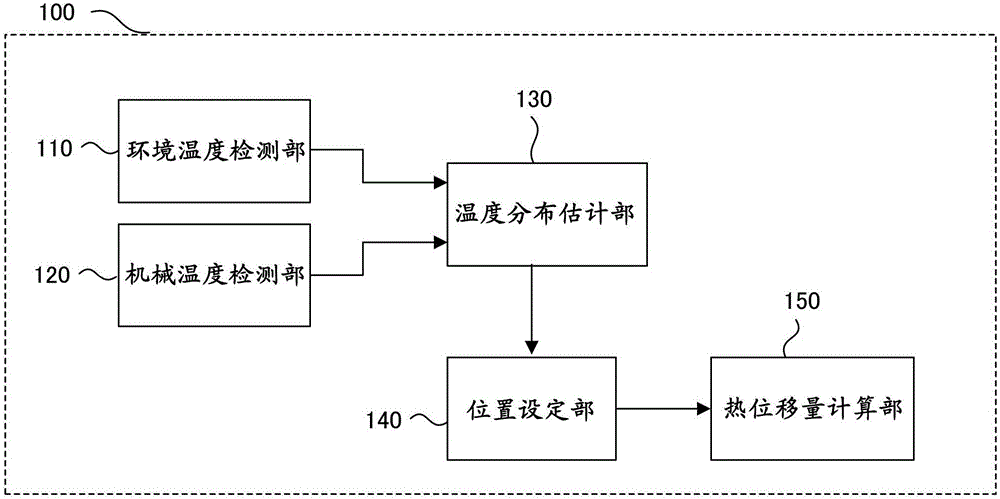
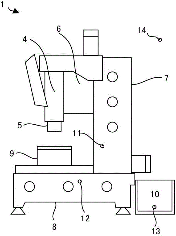
[0044] use image 3 is shown in the flowchart to illustrate the figure 1 performed by the thermal displacement correction device 100, by figure 2 The process of estimating the coolant-induced thermal displacement of machining center 1 is shown.

[0045] Repeatedly while the thermal displacement correction function is valid image 3 processing of the flow chart. In this flowchart, the thermal displacement amount δ caused by the change in ambient temperature and the coolant will be E The description will focus on the thermal displacement of the column body 7 , but the thermal displacement of mechanical structural parts such as the machine base 8 and the spindle mounting table 6 can also be estimated and combined by the same method.

[0046] [Step SA01] The temperature of each part is detected by a temperature sensor and stored in a memory. Expected to pass through the thermal displacement of the ball screw and the main shaft part δ M The calculation interval is the same ...


PUM


Abstract

A thermal displacement compensation device detects the temperature of a machine tool and the temperature of an environment in which the machine tool is placed, and estimates a temperature distribution in a machine component affected by the temperature of the environment from the relationship between the temperature of the machine tool and the temperature of the environment. Based on the estimated temperature distribution in the machine component, a position in the machine tool at which the time constant of the detected temperature matches the time constant of thermal displacement of the machine component affected by the temperature of the environment is found and set. Using temperature at the set position as a revised temperature of temperature detected by the machine temperature detection section, a thermal displacement amount of the machine component is calculated.

Description

technical field [0001] The present invention relates to a thermal displacement correction device of a machine tool, in particular to a thermal displacement correction device of a machine tool capable of performing thermal displacement correction with high precision even with a small number of temperature sensors. Background technique [0002] In the machine tool, the feed screw and the spindle are driven by the electric motor. Therefore, the heat generated by the motor, the frictional heat caused by the rotation of the bearing, and the frictional heat of the contact part between the ball screw of the feed screw and the ball nut cause the spindle and the feed screw to Expansion, causing a change in mechanical position. In addition, due to changes in the ambient temperature of the machine tool and the use of coolant, the temperature of the column and the machine base also changes, resulting in changes in the position of the machine due to stretching and inclination. That is, ...

Claims


Application Information

Patent Timeline
Patent Type & Authority Applications(China)
IPC IPC(8): G05B19/404
CPCG05B19/404G05B2219/37375G05B2219/37431G01K7/427G01K2213/00G05B2219/49026
Inventor 小山泰明
Owner FANUC LTD
Learn More