
Metal molding method and apparatus

a metal and mold technology, applied in the field of metal molding methods and equipment, can solve the problems of deteriorating the quality of the metal mold product, loss of thixotropy of the metallic material in the co-existing state of solid and liquid charged in the cylinder, and risk of flashing, so as to reduce the cycle time, prevent the lubricant from being splashed outward, and avoid pollution of the working environment.

Inactive Publication Date: 2008-02-19
DENSO CORP
View PDF14 Cites 3 Cited by
  • Summary
  • Abstract
  • Description
  • Claims
  • Application Information

AI Technical Summary

Benefits of technology

This approach significantly reduces the molding cycle time by approximately half, enhances the working environment by preventing lubricant splashing and pollution, and ensures better quality of the metallic mold product by maintaining thixotropy during injection.

Problems solved by technology

However, when the material-metering process starts parallel to the solidifying process, the other processes must proceed after the material-metering process has completed, whereby a waiting time is necessary until the mold-clamping process has completed.
However, as described before, if there is a waiting time after the completion of the material-metering process prior to the injection, the thixotropy of the metallic material in the co-existing state of solid and liquid charged in the cylinder is lost, and there may be a problem in that the metallic material is injected while maintaining a high viscosity to deteriorate the quality of the metallic mold product.
However, this method is problematic in that the mold-lubricant coating process is carried out after a mold-opening process and prior to the mold-clamping process so that the metallic material-metering process and the mold-lubricant coating process are simultaneously carried out while the mold is in a open state.
Thus, there is a risk in that molten metal drops down from the tip end of the injection nozzle to adhere to a touch surface of a nozzle or a metallic mold face to result in lack of touching of the nozzle or clamping of the mold, which may cause a risk of flash during the injection.
Also, the mold-lubricant itself may splash out of the mold to worsen the working environment.
According to the metal molding method disclosed in the above publication, although the molding-lubricant coating process requiring a relatively large working time is carried out simultaneously with the material-metering process, the former is independent from processes other than the material-metering process, whereby it does not provide a solution for saving time necessary for the molding cycle.
Thus, a saving of the cycle time cannot be expected because the effect of saving the solidification time by the use of a hot runner is reduced by the process requiring the relatively large working time.

Method used


Image

  • Metal molding method and apparatus
  • Metal molding method and apparatus
  • Metal molding method and apparatus

Examples


Embodiment Construction

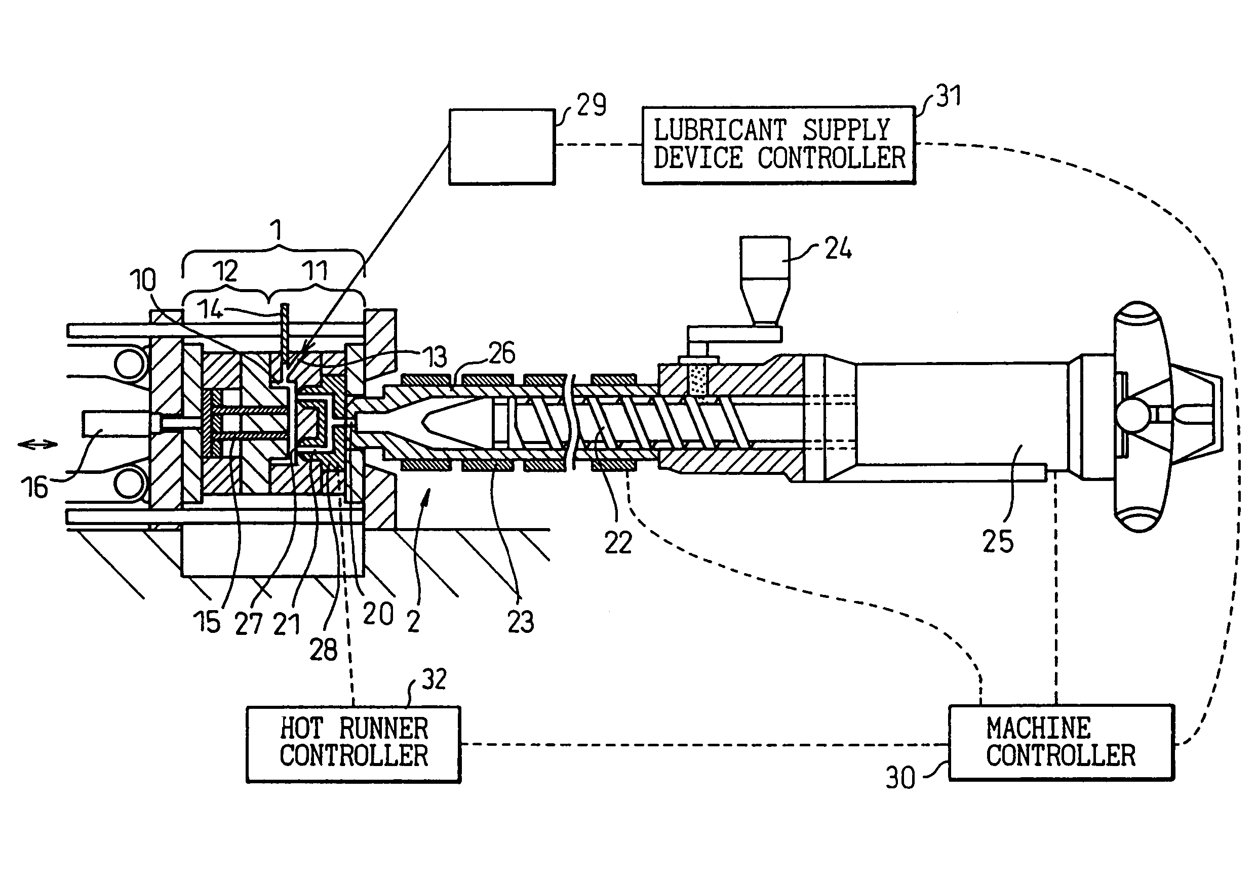
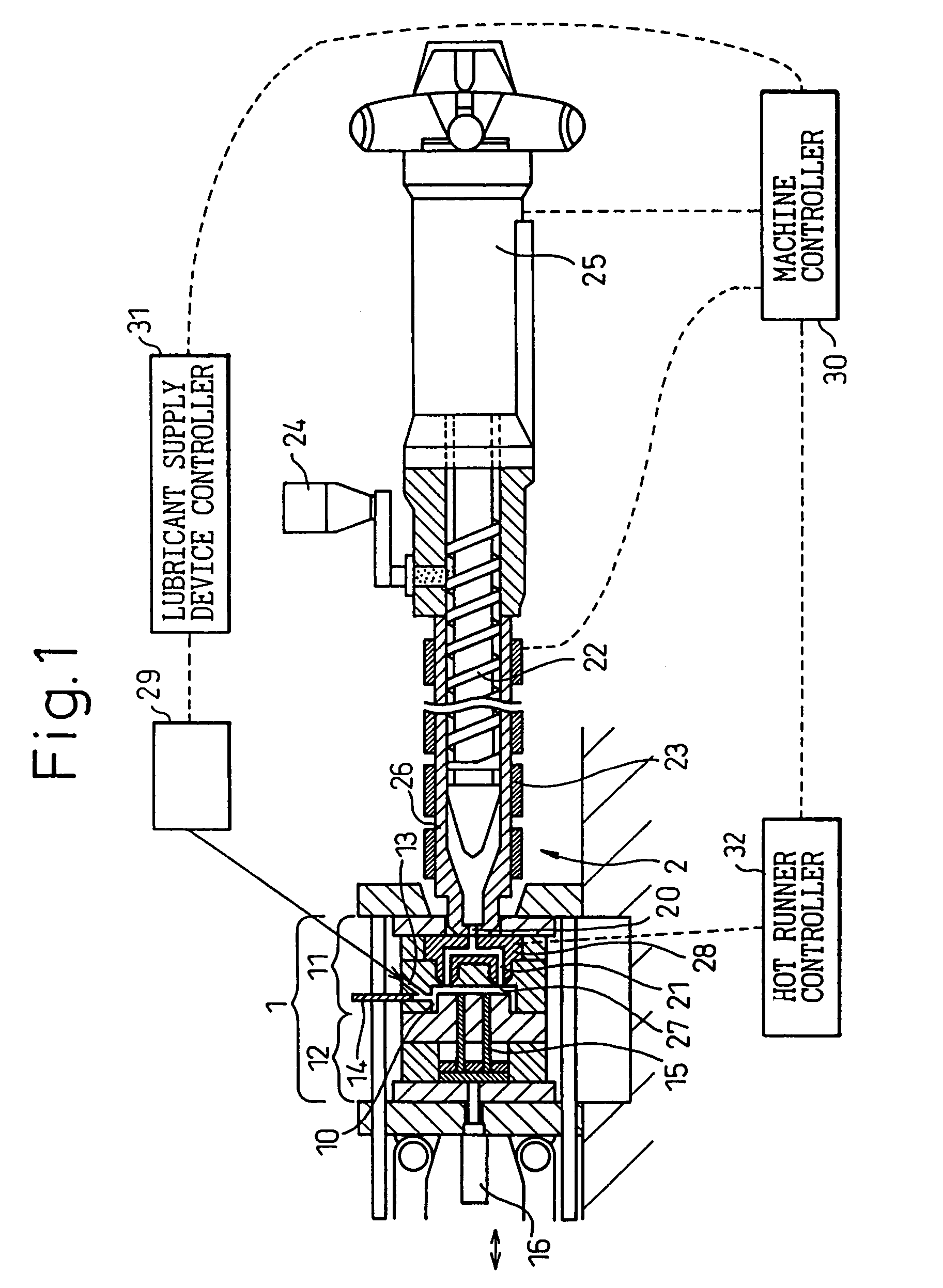
[0021]A method and apparatus for producing a metallic mold product according to one embodiment of the present invention will be described with reference to the attached drawings. FIG. 1 illustrates an over all structure of a thixo-molding apparatus (an apparatus for producing a metallic mold product) used for carrying out a method for molding a metallic mold product according to one embodiment of the present invention. The thixo-molding apparatus (the apparatus for producing a metallic mold product) has a mold 1 including a stationary mold 11 and a movable mold 12. The mold 1 defines a cavity 10 by clamping the stationary mold 11 and the movable mold 12, for molding a metallic material such as a magnesium alloy or others.

[0022]To actuate the movable mold 12, a motorized mold driving mechanism, not shown, is provided so that the movable mold 12 is movable forward and backward relative to the stationary mold 11. Also, the movable mold 12 is provided with an ejector pin 15 and a drivin...


PUM

PropertyMeasurementUnit
cycle timeaaaaaaaaaa
temperatureaaaaaaaaaa
displacementaaaaaaaaaa

Abstract

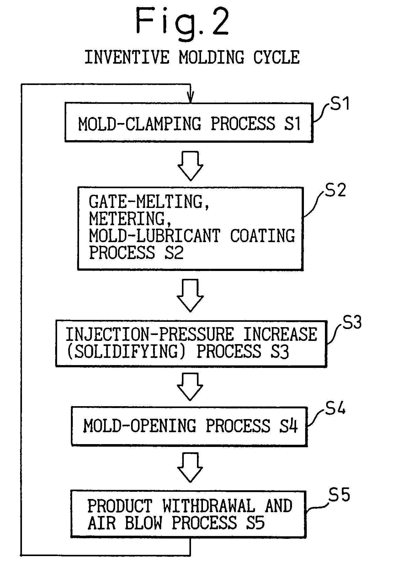
According to the present invention, between the mold-clamping process S1 in which the mold 1 is closed and the injection-pressure increase (solidifying) process S3, the gate-melting process for heating the hot runner 21 to melt the plug (metallic material) of the gate 27, the mold-lubricant coating process for spraying the lubricant onto the wall surface of the cavity 10, and the material-metering process are simultaneously carried out in parallel to each other. Thus, the molding cycle time can be reduced to a great extent.

Description

CROSS-REFERENCE TO RELATED APPLICATIONS[0001]This application is a divisional of U.S. patent application Ser. No. 10 / 229,871 filed on Aug. 28, 2002 now U.S. Pat No. 6,938,669. This application claims the benefit of JP 2001-262007, filed Aug. 30, 2001. The disclosure(s) of the above application(s) is (are) incorporated herein by reference.BACKGROUND OF THE INVENTION[0002]1. Field of the Invention[0003]The present invention relates to a method and apparatus for molding a metal, and particularly magnesium alloy or the like, using an injection-molding machine and a hot runner.[0004]2. Description of the Related Art[0005]In general, a thixo-molding apparatus has an injection mechanism and a clamping mechanism. Mold material, which is metallic chips of magnesium alloy or the like supplied from a hopper, is transferred by a screw into a cylinder heated to a predetermined temperature to be put into a liquidized or a semi-melted state, which develops thixotropy (the property exhibited by cer...

Claims


Application Information

Patent Timeline
Patent Type & Authority Patents(United States)
IPC IPC(8): B22D17/00B22D17/32
CPCB22D17/007B22D17/32Y10S164/90B22D17/2023B22D17/2281
Inventor SUZUKI, HIDEYUKISATO, KOICHIROONODA, RYUICHI
Owner DENSO CORP
Learn More