
Information system

a technology of information system and speedometer, applied in the field of information system, can solve the problems of increasing the number of accidents, unnecessary congestion, and reducing the number of drivers, and achieve the effect of conserving the memory resour

Inactive Publication Date: 2008-02-05
LAST MILE COMMTIVIS
View PDF18 Cites 14 Cited by
  • Summary
  • Abstract
  • Description
  • Claims
  • Application Information

AI Technical Summary

Benefits of technology

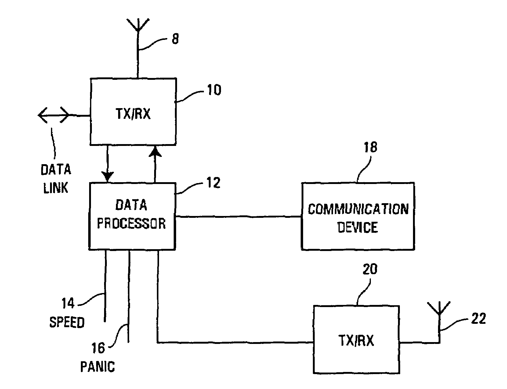
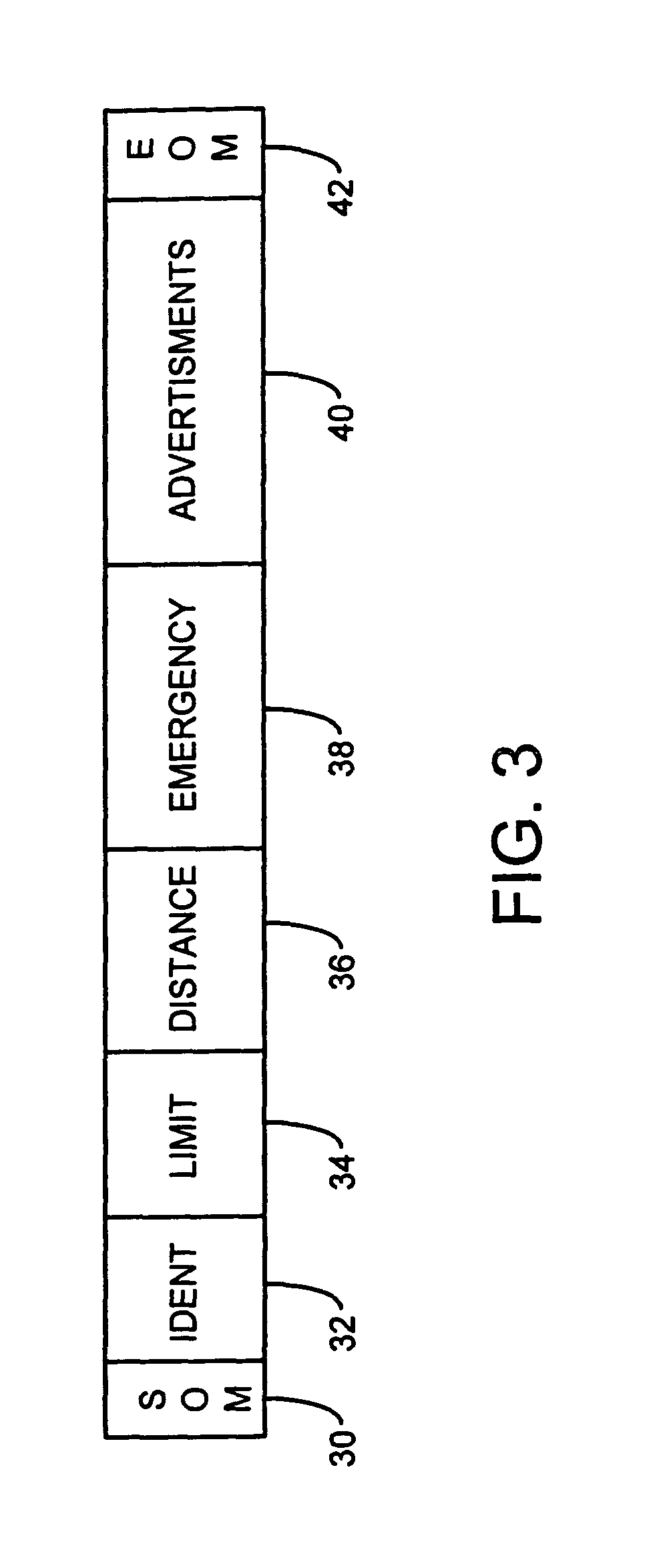
"The present invention is a vehicle information system that uses roadside transmitters to capture and hold data that is indicative of the local speed limit. The system is responsive to the driver's needs and can provide information to the driver in a timely manner. The receiver is designed to respond only to signals from the expected direction, reducing interference from multiple reflections. The system can also be used as an adjunct to GPS-based navigation systems or to alert drivers of potential speed limit violations. The transmitters can transmit data about the speed limit, distance to the next transmitter, and other relevant information. The system can also use the transmitter identity code to navigate by reference to the transmitter's position."

Problems solved by technology

Such a zero tolerance regime might result in many drivers spending a considerable amount of time looking at their speedometer and consequently less time looking at the road.
Furthermore, excessively cautious drivers may drive at a larger margin below the actual speed limit causing unnecessary congestion, possibly frustration amongst other road users and even additional accidents.
Whilst the UK has, in general, a reasonably good sign posting system, it is always possible to miss a road sign when the driver's attention is directed elsewhere.
This may be because of local traffic conditions requiring driver attention.
Furthermore, it is not uncommon, especially on rural roads, for road signs to become obscured by overhanging trees in the summer or to appear as silhouettes when driving into bright sunlight.
There has also been a tendency to increase the number of roadside signs, and this may increase further if roadside advertising or sign sponsorship is allowed, thus giving the driver far more peripheral and nonessential information to sift through before he can identify the local speed limit.
However, if a zero tolerance regime is enforced, then the motorist can no longer rely on this audio clue, and will be forced to examine his speedometer far more frequently and consequently be looking at the road less frequently.

Method used


Image

  • Information system
  • Information system
  • Information system

Examples


Embodiment Construction

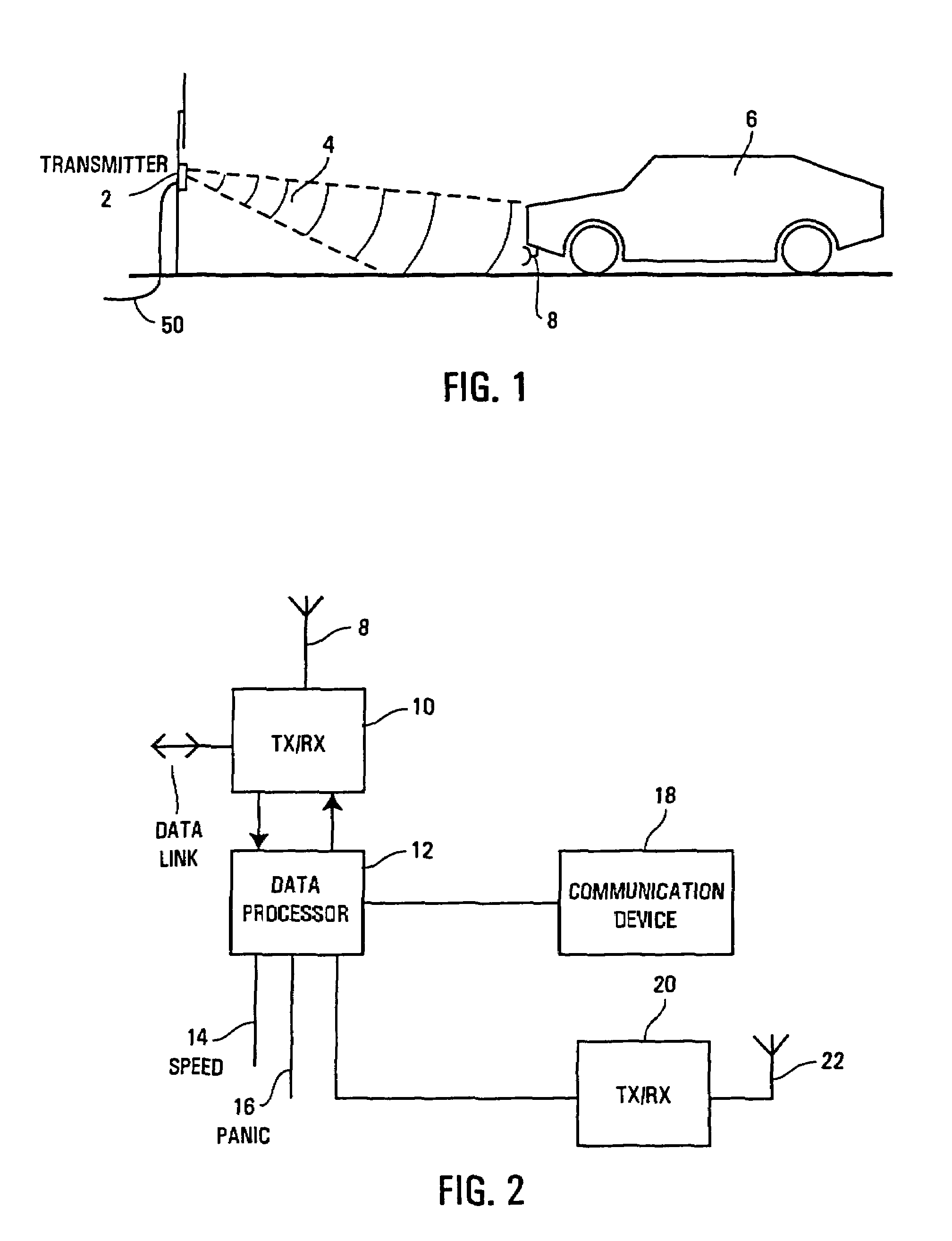
[0063]As shown in FIG. 1, a roadside transmitter 2 constituting an embodiment of the present invention is located adjacent a carriageway such that it emits a well defined radiative beam 4 which can be received by oncoming vehicles 6. The radiative beam 4 is ideally transmitted in the form of a narrowly diverging cone such that it is only received by oncoming vehicles and has little chance of being received by vehicles travelling on the other carriageway. The vehicle 6 carries a directional antenna, schematically illustrated as 8 which faces forwardly, but may be angled to one side slightly in order to face the expected direction of the oncoming transmitters as the vehicle travels. The transmitter 2 may be placed on any convenient housing or support beside the carriageway, but most conveniently may be incorporated within pre-existing street furniture such as road signs, or “belisha beacons” used to signal the presence of pedestrian crossings. When the transmitter is associated with a...


PUM


Abstract

An information system is provided for transmitting data into a local area surrounding the transmitter. The transmitter may be used to provide information to pedestrians, or to passing road traffic. Data is stored in a local memory 64 associated with the transmitter such that data stored in the memory can be repeatedly and frequently transmitted to users 70 having suitable reception apparatus 18 in the vicinity of the transmitter.

Description

CROSS REFERENCE TO RELATED APPLICATION[0001]This is a divisional patent application of U.S. patent application Ser. No. 09 / 680,348 filed on Oct. 5, 2000 now U.S. Pat. No. 6,606,033.FIELD OF THE DISCLOSURE[0002]The present invention relates to an information system, and in particular to a local information system which may be used by pedestrians or as a vehicle information system. Such an information system may be arranged to provide data concerning local services, may allow local businesses to advertise or may advise the locally pertaining speed limits to the driver of a vehicle. The system may be used in some pedestrian environments, for instance airports or railway stations, to deliver relevant contextual information such as timetables, arrival and departure data and so on.BACKGROUND OF THE DISCLOSURE[0003]There have been proposals to crack down on speeding. There has even been a suggestion of zero tolerance of minor speed violations. In the United Kingdom, the Council for the Pro...

Claims


Application Information

Patent Timeline
Patent Type & Authority Patents(United States)
IPC IPC(8): G08G1/01G08G1/0967
CPCG06Q30/02G08G1/005G08G1/096716G08G1/096725G08G1/09675G08G1/096758G08G1/096775G08G1/096783G08G1/096791
Inventor CROCKER, TIMOTHY R.BRANDWOOD, JOHN D.BISHOP, FRANK M.
Owner LAST MILE COMMTIVIS
Learn More