PWM signal generation circuit and PWM control circuit

a control circuit and signal generation technology, applied in pulse manipulation, pulse technique, instruments, etc., can solve the problems of significant impact, labor-intensive and time-consuming to change the duty ratio, and the duty ratio varies accordingly, so as to reduce the impact of temperature changes, precise duty ratio, and easy operation

Inactive Publication Date: 2008-02-05
AUTONETWORKS TECH LTD +2
View PDF8 Cites 3 Cited by
  • Summary
  • Abstract
  • Description
  • Claims
  • Application Information

AI Technical Summary

Benefits of technology

[0010]When the voltage level depending on the amount of charge in the capacitor exceeds the charging threshold, the output of the comparator is brought to low state (i.e., where an open-collector output inside the comparator turns on to output a low level signal). This causes a discharged current from the capacitor to flow into a ground through a second feedback line and the output side of the comparator, which slowly reduces the amount of charge in the capacitor. Along with this, part of a current from the voltage-dividing circuit and a current flowing through the first resistor flow into the ground through the output side of the comparator. Thus, the voltage level provided to the first input terminal of the comparator falls below the charging threshold (this voltage level is hereinafter referred to as the “discharging threshold”).
[0017]With such an arrangement, the duty ratio of the PWM signal can easily be adjusted by only changing the resistance ratio between the second resistor and the third resistor, for example. Furthermore, if the circuit constant varies due to ambient temperature changes or the degradation of circuit elements, and thus the charging threshold and the discharging threshold vary, the charging time period and the discharging time period of the capacitor also vary accordingly. Consequently, the ratio between the charging time period and the discharging time period of the capacitor, or the duty ratio of the PWM signal, can be kept substantially constant.
[0020]In the case, for example, where a duty ratio of the PWM signal of, for example, 20% or less or 80% or more is desired, this may be achieved by changing the resistance ratio between the second resistor and the third resistor. However, use of a resistor of too large of a resistance may increase the susceptibility to temperature changes and the like. Therefore, according to the arrangement, charging of the capacitor is accomplished by allowing a current to flow from the power line through at least the second resistor, while discharging of the capacitor is accomplished through the third resistor.<The Invention According to a Fifth Aspect>
[0021]According to the arrangement, there is provided a circuit element with the same temperature characteristics as a current regulating element for a current regulating means on the RC serial circuit. Therefore, even with temperature changes, the impact on the duty ratio of the PWM signal is minimized because the amount of the charging current and the amount of the discharging current vary in the same manner.<The Invention According to a Sixth Aspect>
[0022]According to the arrangement, because the current regulating means and the circuit element are provided within the same chip, they will be equally affected by any ambient temperature changes. As a result, a PWM signal can be generated with a more precise duty ratio.<The Invention According to a Seventh Aspect>
[0023]According to the arrangement, actuation and termination of PWM control can be easily switched by only turning on and off a switch means.<The Invention According to an Eighth Aspect>

Problems solved by technology

This poses a problem in that it is labor-intensive and time-consuming to change the duty ratio.
However, the PWM control circuit in Japanese Laid-Open Patent No. 7-154965 has a problem in that, as the circuit constant of a PWM control circuit varies due to changes in the ambient temperature, degradation of circuit elements, and the like, the duty ratio varies accordingly.
Such a problem may have a significant impact, particularly on a vehicle etc., which is often used in an environment where the ambient temperature changes drastically.

Method used


Image

  • PWM signal generation circuit and PWM control circuit
  • PWM signal generation circuit and PWM control circuit
  • PWM signal generation circuit and PWM control circuit

Examples


first embodiment

[0029]A first embodiment of the invention will now be described with reference to FIGS. 1 to 3(A)-3(E).

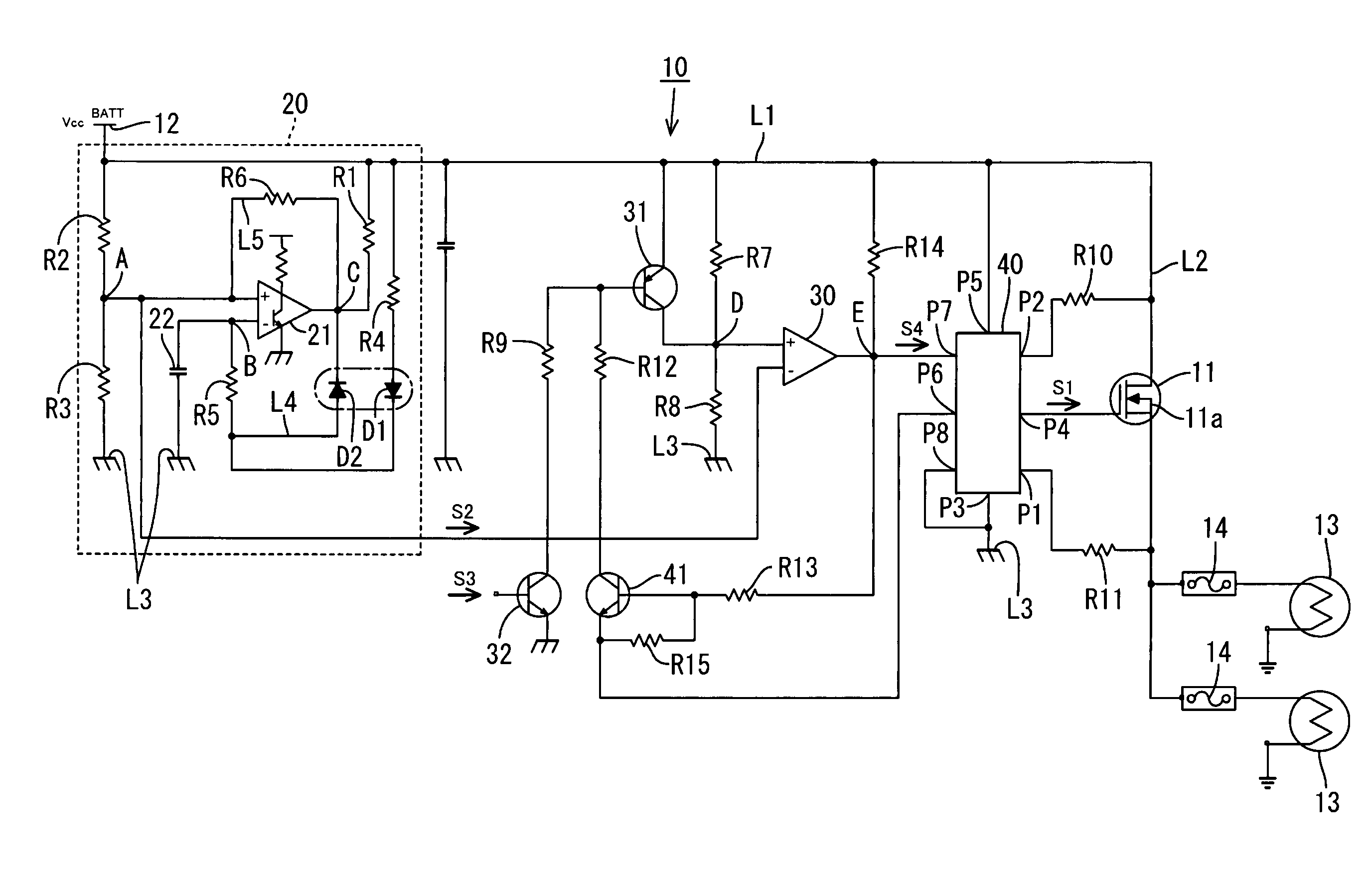
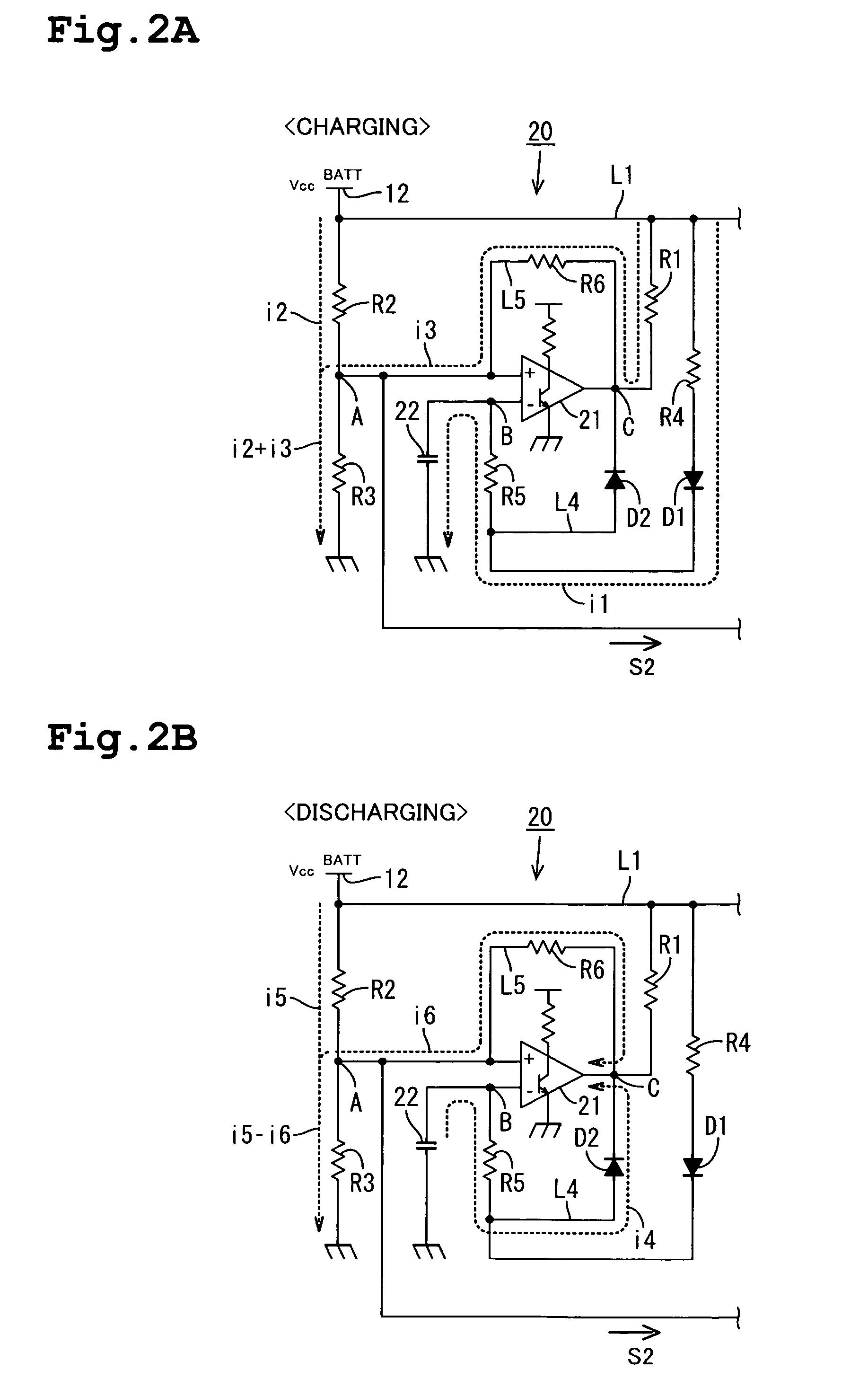
[0030]A PWM control circuit 10 of the embodiment is for providing PWM control of a supply of power from a power supply 12 (e.g. a battery) to a pair of headlamps 13, 13 coupled to an output side of a thermal FET 11 by providing a PWM (Pulse Width Modulation) signal S1 as a control signal to an input of a thermal FET 11, which serves as a semiconductor switch, to turn the thermal FET 11 on and off.

1. Configuration of the Embodiment

(1) General Configuration of the PWM Control Circuit

[0031]As shown in FIG. 1, the thermal FET 11 has a drain connected to a power line L1 coupled to a high-voltage side of the power supply 12, and a source respectively connected to the pair of headlamps 13, 13 through fuses 14, 14. The PWM control circuit 10 is arranged to cause a PWM signal generation circuit 20 to generate an output signal S2 as a PWM signal, and provide it to a gate of the thermal FET 1...

second embodiment

[0060]FIG. 4 shows a second embodiment (corresponding to the invention according to a second aspect). The difference from the first embodiment primarily resides in the use of an operational amplifier 50 in place of the comparator 21. The other elements are similar to those of the first embodiment. Therefore, only the differences will be described, using the same reference numerals as in the first embodiment and omitting duplicated descriptions.

[0061]FIG. 4 is a circuit diagram illustrating a configuration of the second embodiment. FIG. 4 shows only the PWM signal generation circuit 51 portion of the PWM control circuit. As shown in FIG. 4, contrary to FIG. 1 for the first embodiment, the second embodiment adopts an arrangement in which an operational amplifier 50 is used in place of the comparator 21. In addition, the output resistor R1 is removed to omit a connection between an output of the operational amplifier 50 and the power line L1. The state in which a high-potential side tr...


PUM


Abstract

A PWM signal generation circuit and a PWM control circuit are provided in which the duty ratio is easily changed and which can also avoid adverse impact from ambient temperature changes and the like. At the beginning of charging a capacitor with a current flow, a voltage level at a connection point between the negative input terminal of a comparator and the capacitor is still below a charging threshold. When the charging threshold is exceeded, the comparator is inverted to a low state and a current flows into an output point of the comparator to start discharging the capacitor. At the beginning of discharging from the capacitor, the voltage level at the connection point is still above the discharging threshold. However, when the voltage level falls below the discharging threshold, the comparator returns to a high state, and the charging operation again takes over.

Description

BACKGROUND OF THE INVENTION[0001]1. Field of the Invention[0002]The present invention relates to a Pulse Width Modulation (PWM) signal generation circuit and a PWM control circuit.[0003]2. Description of the Related Art[0004]Each country has its own safety standards, for example, for headlamps of vehicles. According to some safety standards, headlamps are required to be illuminated while driving in broad daylight at a brightness of a predetermined proportion (for example, 12.5% and 22.5%) to that of the nighttime. Therefore, some headlamps are conventionally illuminated with PWM control for headlighting during daylight (Daylights) in a predetermined proportion to headlighting at nighttime. Some arrangements for the PWM control accomplish the lighting control of headlamps based on PWM signals, for example, generated by a microcomputer or a special purpose IC.[0005]Those arrangements for the PWM control with the microcomputer and the like, however, require the voltage of a battery mou...

Claims


Application Information

Patent Timeline
Patent Type & Authority Patents(United States)
IPC IPC(8): H03K7/08G05F5/00
CPCB60Q1/1423H03K7/08B60Q2400/30
Inventor ASADA, KAZUHIRO
Owner AUTONETWORKS TECH LTD
Why Eureka
Try Eureka