
Method and apparatus for facilitating the operation of an on-site energy storage system to co-optimize battery dispatch

Active Publication Date: 2017-05-09
SWELL ENERGY INC
View PDF9 Cites 40 Cited by
  • Summary
  • Abstract
  • Description
  • Claims
  • Application Information

AI Technical Summary

Benefits of technology

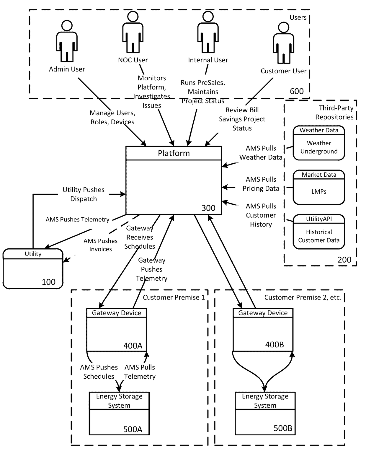
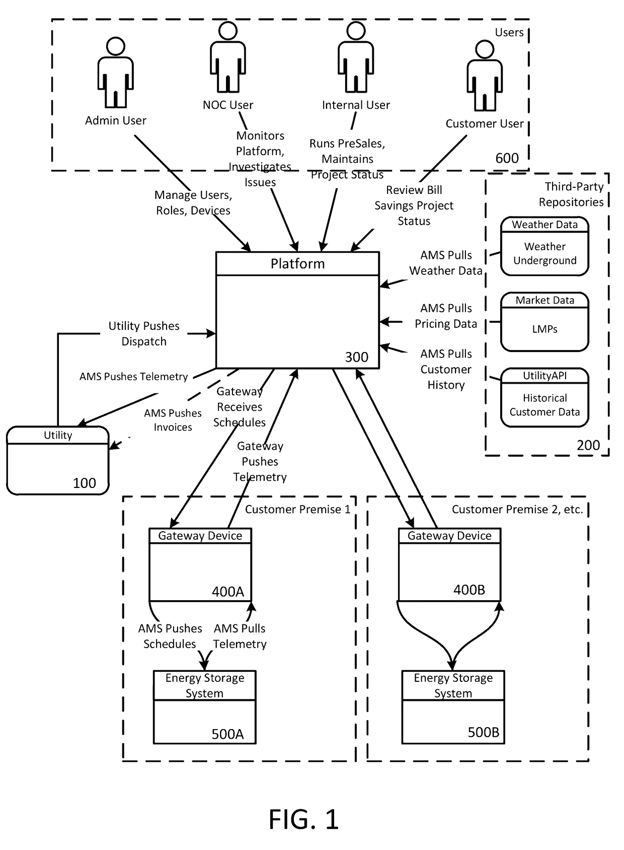
The present invention provides a system for optimizing the use of on-site energy assets, such as solar panels or wind turbines, to co-optimize energy dispatch and reduce costs for customers. The system includes a platform apparatus and a gateway apparatus, which work together to calculate site load curves, optimize energy consumption, and control the use of on-site energy assets in real-time. The system can also receive utility requests to reduce grid-supplied energy consumption and provide instructions to control on-site energy asset usage and grid-supplied electric consumption. The technical effects of the invention include reducing peak demand charges, improving energy efficiency, and providing cost savings for customers.

Problems solved by technology

However, the customer then bears the cost of having the on-site energy storage system installed, maintained, and operated and, furthermore, bears the risk that the cost savings do not justify the expenditures.
Moreover, the utilities generally have no control over the deployment and operation of the on-site energy storage systems deployed in the field and cannot rely on these resources like other traditional generators as firm capacity products, for purposes such as resource adequacy.

Method used


Image

  • Method and apparatus for facilitating the operation of an on-site energy storage system to co-optimize battery dispatch
  • Method and apparatus for facilitating the operation of an on-site energy storage system to co-optimize battery dispatch
  • Method and apparatus for facilitating the operation of an on-site energy storage system to co-optimize battery dispatch

Examples


Embodiment Construction

[0036]Some example embodiments will now be described more fully hereinafter with reference to the accompanying drawings, in which some, but not all embodiments are shown. Indeed, the example embodiments may take many different forms and should not be construed as limited to the embodiments set forth herein; rather, these embodiments are provided so that this disclosure will satisfy applicable legal requirements. Like reference numerals refer to like elements throughout. The terms “data,”“content,”“information,” and similar terms may be used interchangeably, according to some example embodiments, to refer to data capable of being transmitted, received, operated on, and / or stored. Moreover, the term “exemplary”, as may be used herein, is not provided to convey any qualitative assessment, but instead merely to convey an illustration of an example. Thus, use of any such terms should not be taken to limit the spirit and scope of embodiments of the present invention.

[0037]The term energy ...


PUM


Abstract

Various embodiments are provided for facilitating the operation and control of a fleet of on-site energy assets and optimizing energy dispatch across the fleet, thereby facilitating the use of the on-site energy assets instead of grid-supplied electric consumption. An example system may comprise a central platform and a plurality of on-site gateway devices configured to perform on-site asset control. An example method may comprise receiving a service availability call, performing fleet-level optimization, generating a set of site-level schedules, and causing, as a function of the site-level schedules, real-time on-site asset control. Other embodiments provide for determining a location of each grid-connected energy consumer at which to reduce grid-supplied energy consumption, determining an amount of a reduction of grid-supplied energy consumption, and transmitting a signal to each corresponding gateway device located at the determined location, the signal comprising data indicative of instructions for performing on-site energy dispatch.

Description

TECHNOLOGICAL FIELD[0001]Embodiments of the present invention relate generally to facilitating the operation and control of a fleet of on site (e.g., customer-sited) energy assets that may include energy storage systems, renewable fuel or diesel generators, gas turbines, or the like, and in particular to methods, apparatus, and computer program products for optimizing energy dispatch across this fleet to provide an energy provider (e.g., a utility, a system operator, or a retail energy provider) with firm capacity, for example, for purposes of resource adequacy, other services or market products at specific market nodes and to reduce the electric costs for end customers with these controllable assets located on-premises.BACKGROUND[0002]Conventional systems require electric transmission and distribution system operators and utilities to build infrastructure to support peak demand, the costs of which are passed on to the customer, for example, via tariffs including demand response pro...

Claims


Application Information

Patent Timeline
IPC IPC(8): G05D17/00G05D3/12G05D9/00G05D5/00G05D11/00H02J7/00G05F1/66
CPCG05F1/66H02J7/0021Y04S10/14H02J3/32Y04S40/12Y04S50/12G06Q30/04G06Q50/06H02J2203/20H02J13/00006H02J13/00034Y02E40/70Y02E60/00Y04S10/50Y04S40/20G05B15/02H02J3/003H02J13/00
Inventor LEE, JA-CHIN AUDREYNOONE, COREYKNOX, KATE
Owner SWELL ENERGY INC
Learn More