
Apparatus and method for providing a modular sliding door mechanism

a sliding door and accessory technology, applied in the field of vehicle doors, can solve the problems of complex system, non-modular, cumbersome installation, and required seal for

Active Publication Date: 2008-02-05
STRATTEC POWER ACCESS
View PDF146 Cites 32 Cited by
  • Summary
  • Abstract
  • Description
  • Claims
  • Application Information

AI Technical Summary

Benefits of technology

[0010]A modular drive assembly for a sliding door, comprising: a guide track having a hinge assembly slidably received therein; a pair of pulleys disposed on either end of said guide track, said pair of guide pulleys being disposed adjacent to a path of travel of said hinge assembly within said guide track, said path of travel being defined by a closed door limit and an open door limit; a pair of cables each having an end that is secured to said hinge assembly and the other end is secured to a cable drum of a motor drive unit mounted to said guide track, said motor drive unit being configured to rotate said cable d

Problems solved by technology

These systems are complex, non-modular, cumbersome to install, and require the cables to be routed through the vehicle, the system, tensioned and then secured to the hinge during assembly of the system on the vehicle (e.g., on the assembly line).
The previously mentioned difference in required seal force is typically due to the inefficiency of transferring the force from the cable to the door via the center roller hinge / roller track / door interface.
In addition, non-modular power drive systems include many components that must be installed together on the assembly line.
Accordingly, many power sliding doors and their associated non-modular drive systems require significant work to install on the assembly line as multiple separate components must be installed and tested during the vehicle assembly process.
Moreover, these systems impact on the available real estate within the vehicle.

Method used


Image

  • Apparatus and method for providing a modular sliding door mechanism
  • Apparatus and method for providing a modular sliding door mechanism
  • Apparatus and method for providing a modular sliding door mechanism

Examples


Embodiment Construction

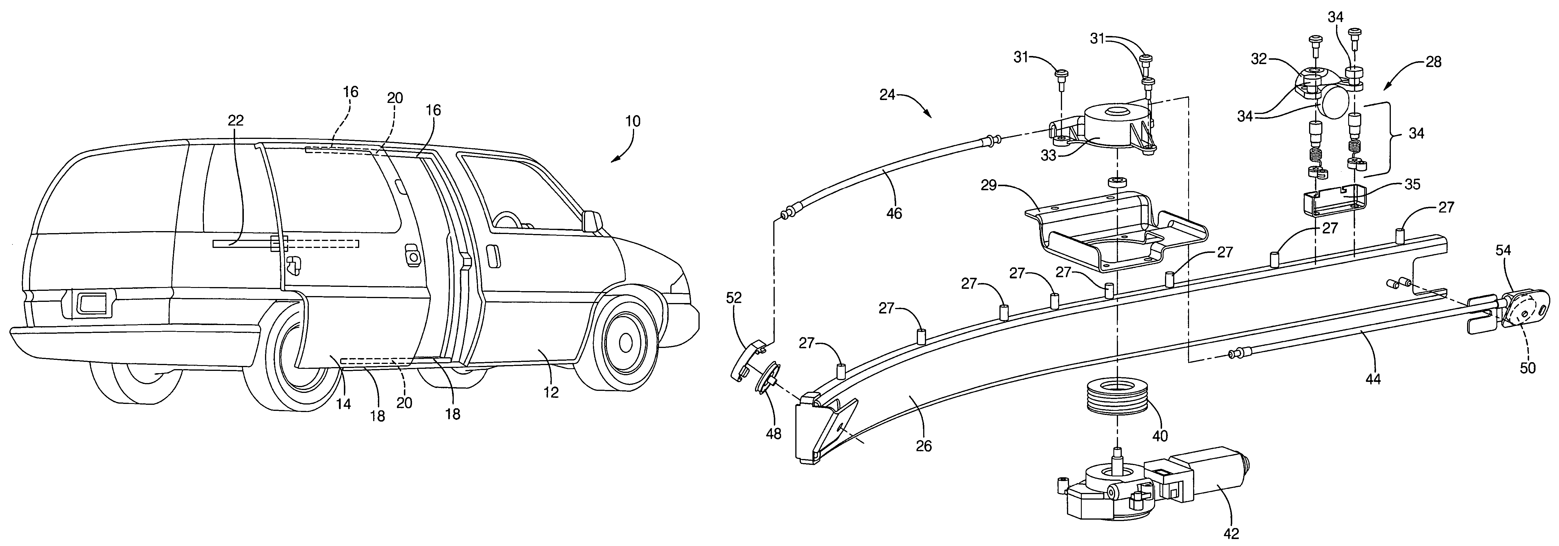
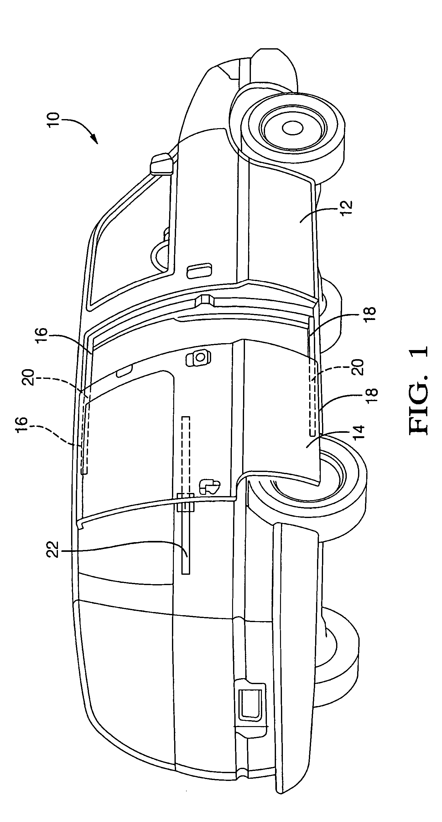
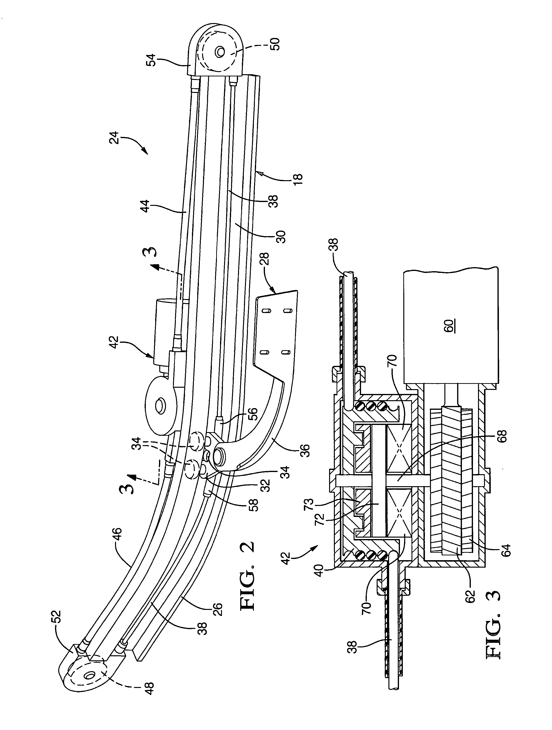
[0037]Exemplary embodiments of the present invention relate to an apparatus and method for providing a modular drive unit that is easy to install and provides the necessary components for opening and closing the power sliding door wherein efficient transference of the seal force is achieved.

[0038]Prior apparatus and methods for providing and / or effectuating moving of a sliding door of a vehicle are found in U.S. Pat. Nos. 5,046,283; 5,313,795; 5,319,880; 5,319,881 and 5,323,570 the contents of which are incorporated herein by reference thereto.

[0039]A modular system of an exemplary embodiment provides a means for efficient seal force transfer while simplifying the installation process thus, decreasing the associated manufacturing costs. In one embodiment, the proposed drive unit will drive off of the lower roller hinge and will be located on the lower sliding door track. The system will be modular so that all the components needed for the power sliding door drive unit will be attach...


PUM


Abstract

A modular drive assembly for a sliding door, comprising: a guide track having a hinge slidably received therein; a pair of pulleys disposed on either end of the guide track; a pair of cables each having an end that is secured to the hinge and the other end is secured to a cable drum of a motor drive unit mounted to the guide track, the motor drive unit being configured to rotate the cable drum, wherein the cable drum is also capable of freely rotating within the motor drive unit when the motor drive unit is not rotating the cable drum, wherein rotation of the cable drum causes the hinge to move in the guide track as one of the cables wraps onto the cable drum while the other one of the cables wraps off of the cable drum.

Description

CROSS REFERENCE TO RELATED APPLICATIONS[0001]This application claims the benefit of U.S. Provisional application Ser. No. 60 / 455,989, filed Mar. 19, 2003, the contents of which are incorporated herein by reference thereto.[0002]This application is also related to co-pending U.S. patent application Ser. No. 10 / 798,792, filed contemporaneously with the present application, the contents of which are incorporated herein by reference thereto.TECHNICAL FIELD[0003]The present application relates to vehicle doors and more particularly the present application relates to an apparatus and method for providing a modular sliding door mechanism.BACKGROUND[0004]A typical vehicle is manufactured with a plurality of openable doors. Each door is typically mounted on hinges within a door opening. Some larger vehicles have sliding doors that slide from an open position to closed position thus, egress and ingress of the vehicle is possible without requiring a large open area beside the vehicle to allow ...

Claims


Application Information

Patent Timeline
IPC IPC(8): E05F11/00
CPCE05F15/643E05Y2201/216E05Y2201/246E05Y2201/462E05Y2201/664E05Y2900/531E05Y2201/654
Inventor ROGERS, JR., LLOYD W.ORR, BRIANHAMMINGA, JEFF S.LINDSAY, THEODORE J.
Owner STRATTEC POWER ACCESS
Learn More