
Apparatus and method for stenting bifurcation lesions

a bifurcation and apparatus technology, applied in the field of balloon catheters, can solve the problems of unsuitable treatment for prior art stenting procedures, difficult and time-consuming process, and difficult to insert guide wires into side branch vessels, etc., and achieve the effect of simple and efficient means

Active Publication Date: 2008-01-29
SUHR WILLIAM S +1
View PDF4 Cites 32 Cited by
  • Summary
  • Abstract
  • Description
  • Claims
  • Application Information

AI Technical Summary

Benefits of technology

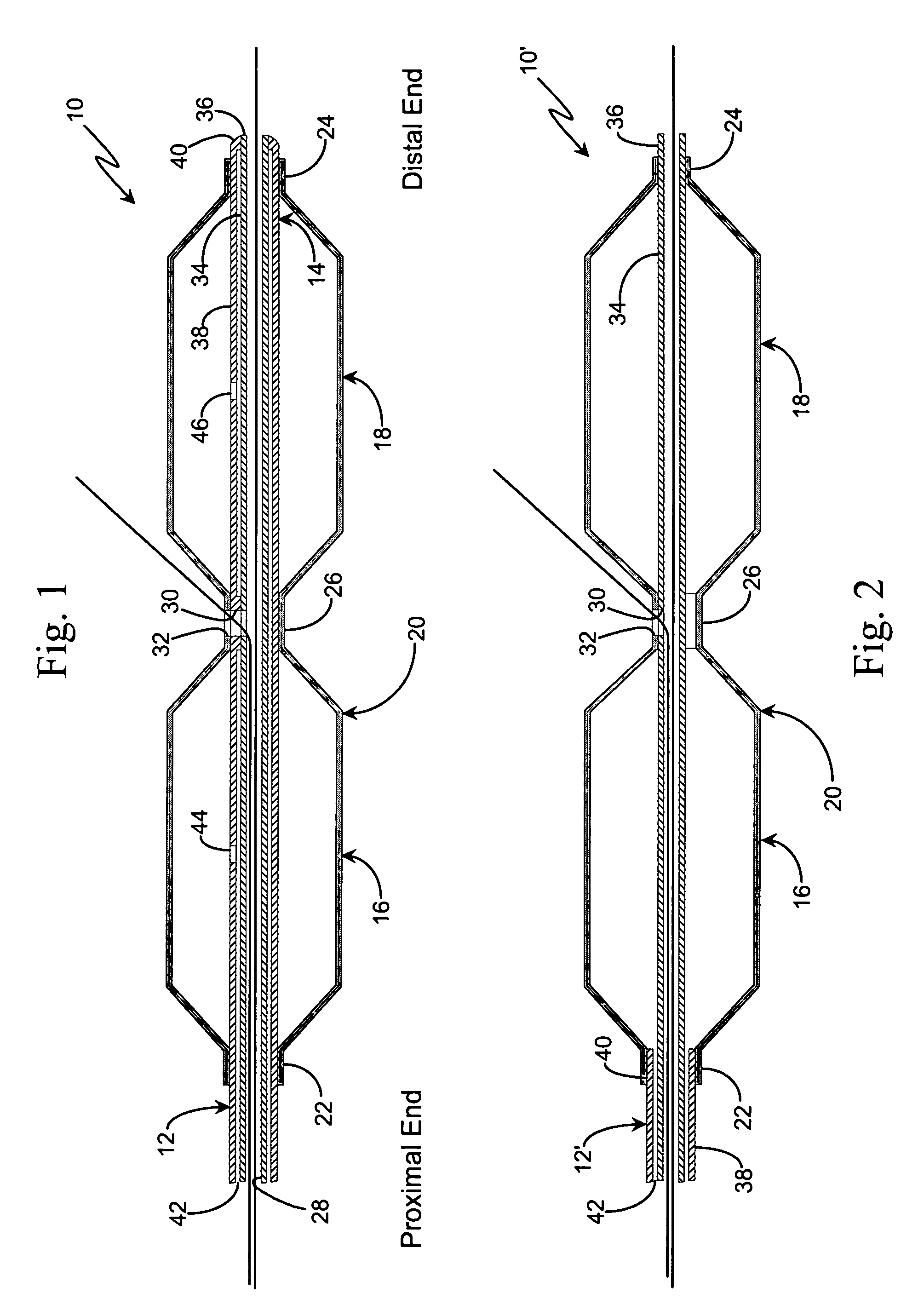
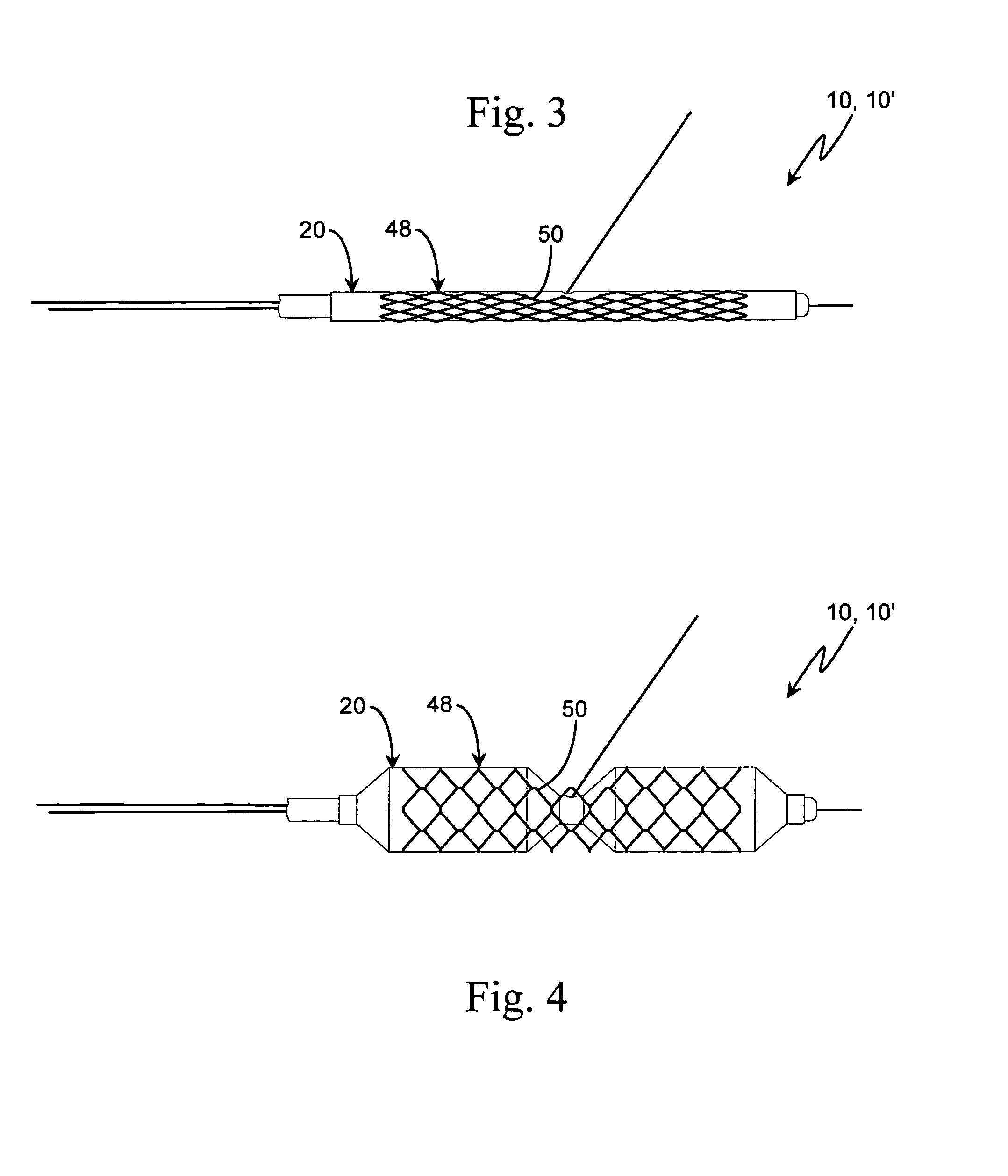
[0008]Thus, the balloon catheter of the present invention provides a simple and efficient means for treating a condition of a blood vessel occurring at or near a bifurcation of the blood vessel. Since the balloon catheter requires the pre-positioning of the first and second guide wires in the main and side branch vessels, respectively, the second guide wire can remain in place in the side branch vessel after a pre-dilation procedure, thereby eliminating the need to withdraw the second guide wire prior to stenting the main vessel. Also, since the second guide wire is threaded through the lateral port between the first and second balloon portions, the second guide wire will guide the placement of the first and second balloon portions across the opening to the side branch vessel. In addition, because the second guide wire is threaded through the stent before it is introduced into the vessel, the second guide wire may remain in position while the stent is deployed in the main vessel, thereby eliminating the need to thread the second guide wire through the stent after the stent is deployed in the main vessel. Furthermore, since a second stent may be deployed in the side branch vessel on the second guide wire, the first guide wire may remain in the main vessel during the stenting of the side branch vessel in the event the main vessel requires a subsequent treatment.

Problems solved by technology

Prior art stenting procedures often are unsuitable for treating a condition of a blood vessel occurring at or near a bifurcation of the blood vessel, that is, the intersection of a main vessel with a side branch vessel.
This process can be quite difficult and time consuming.
Furthermore, the stenting of the main vessel may shift plagues and thereby close off the side branch vessel, making it extremely difficult to insert the guide wire into the side branch vessel.
Consequently, difficulty may be experienced in inserting the second guide wire back into the side branch vessel prior to stenting or otherwise re-treating the side branch vessel.

Method used


Image

  • Apparatus and method for stenting bifurcation lesions
  • Apparatus and method for stenting bifurcation lesions
  • Apparatus and method for stenting bifurcation lesions

Examples


Embodiment Construction

[0018]The present invention is directed to a balloon catheter which is particularly useful in delivering and deploying a stent at or adjacent a bifurcation in a blood vessel. The invention may be used with any conventional balloon catheter delivery system, including the over-the-wire balloon system or the rapid exchange balloon system. In addition, the invention may be used to deploy any conventional balloon-deployable stent. Therefore, the scope of the present invention should not be limited to the exemplary delivery system and stents discussed below.

[0019]Referring to FIG. 1, the segmented balloon catheter of the present invention, which is indicated generally by reference number 10, is shown to comprise an elongated shaft 12 which includes a distal end 14 and a proximal end (not shown), a first cylindrical balloon portion 16 which is mounted on the distal end, and a second cylindrical balloon portion 18 which is mounted on the distal end adjacent the first balloon portion. Each b...


PUM


Abstract

A balloon catheter for use in treating a condition of a vessel occurring near a bifurcation defined by the intersection of a main vessel with a side branch vessel comprises a shaft which comprises a proximal end, a distal end, a longitudinal passageway extending between the proximal and distal ends, and a transverse hole extending from the passageway. The balloon catheter also comprises a balloon head which is mounted on the shaft and which comprises an elongated balloon portion having a generally uniform outer diameter surface, an intermediate portion secured to the shaft proximate the hole, a port formed in the intermediate portion in alignment with the hole, and a portal extending between the outer diameter surface and the intermediate portion. In this manner, a proximal end of a first guide wire which is pre-positioned in the main vessel may be inserted into the distal end of the shaft and threaded through the longitudinal passageway and out the proximal end of the shaft, and a proximal end of a second guide wire which is pre-positioned in the side branch vessel may be inserted into the portal, the port and the hole and threaded through the longitudinal passageway and out the proximal end of the shaft.

Description

[0001]This application is a continuation-in-part of U.S. patent application Ser. No. 10 / 201,755, which was filed on Jul. 22, 2002 now U.S. Pat. No. 6,761,734.BACKGROUND OF THE INVENTION[0002]The present invention relates to an apparatus and method for stenting a blood vessel. More particularly, the invention relates to a balloon catheter which may be used to deploy one or more stents in a bifurcation of the blood vessel in order to treat an occlusion or lesion occurring in or near the bifurcation.[0003]Balloon catheters are commonly used to treat certain conditions of a blood vessel, such as a partial or total occlusion or lesion of the vessel which may be caused by, for example, atherosclerotic plagues or thrombosis. In an angioplasty procedure, the balloon portion of the catheter is advanced over a guide wire to the site of the occlusion and inflated to compress the occlusion and thereby restore normal blood flow through the vessel. In some instances, a stent may be implanted in t...

Claims


Application Information

Patent Timeline
Patent Type & Authority Patents(United States)
IPC IPC(8): A61F2/06A61F2/82A61M25/00
CPCA61F2/954A61F2/958A61F2/856A61F2002/821A61F2250/006A61M25/1011A61M25/10A61M25/09A61F2/82A61L27/54
Inventor SUHR, WILLIAM S.SUHR, HANNAH S.
Owner SUHR WILLIAM S
Learn More