
Electric fireplace having a fire simulating assembly

a technology of simulating assembly and electric fireplace, which is applied in the direction of combustion types, stoves or ranges, instruments, etc., can solve the problems of short hiberarchy or natural vision of flames produced by the above-mentioned simulating assembly, mechanical impression of flames, and inability to produce flames, etc., to achieve the effect of prolonging the life of the firepla

Inactive Publication Date: 2008-01-29
CHEN YUEPENG
View PDF6 Cites 20 Cited by
  • Summary
  • Abstract
  • Description
  • Claims
  • Application Information

AI Technical Summary

Benefits of technology

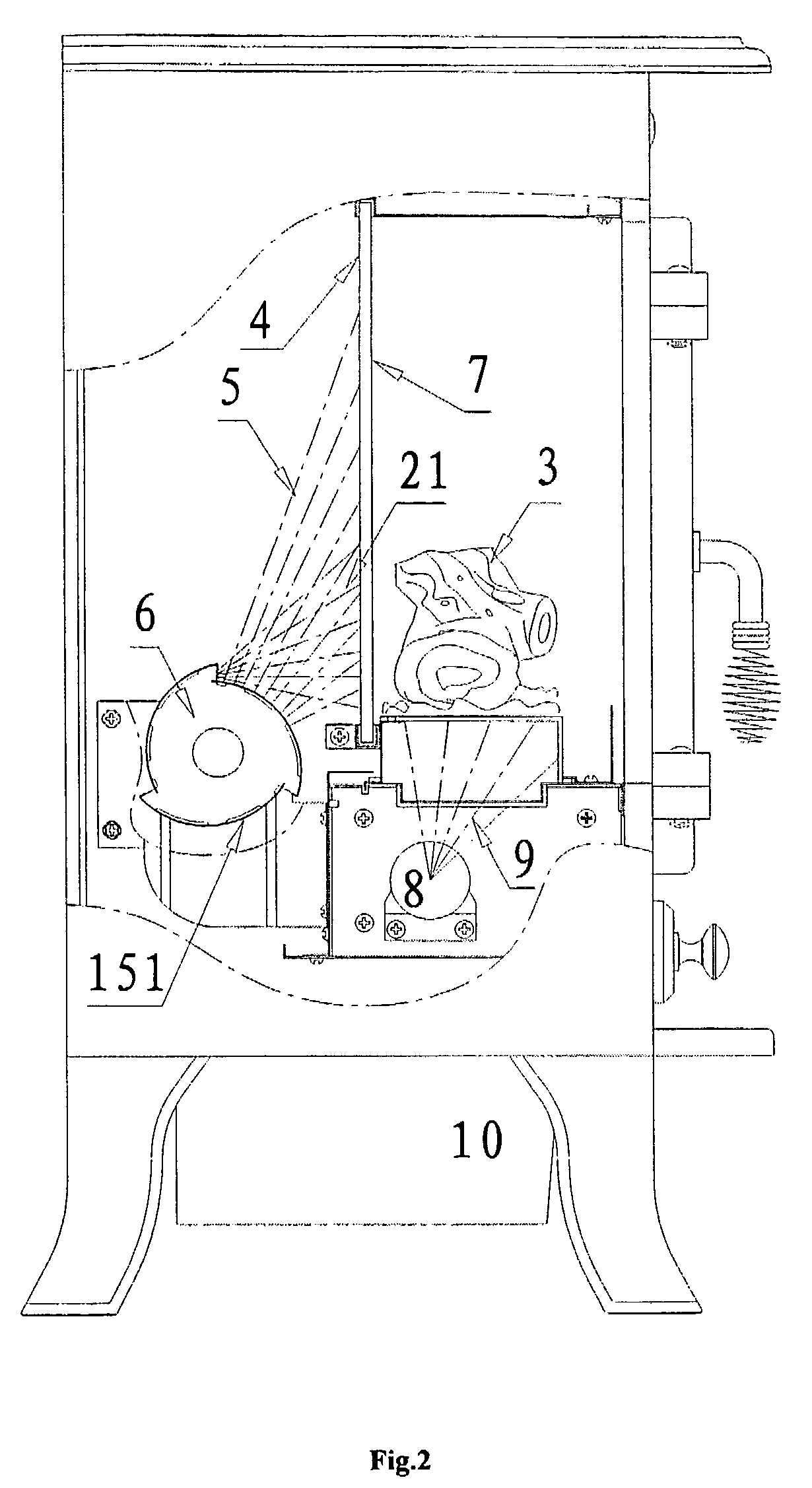
"The present invention is an improved electric fireplace with a flame simulating assembly that produces a rising, leaping, and natural flame to solve the problems of previous electric fireplaces. The flame simulating assembly includes a semitransparent light filter screen, a mirror glass wall, and a dynamic light source with centrifugal blades. The centrifugal blades rotate around the center of the light source and create an effect of flickering flames. The invention also includes several flicking boards with flame color set at the periphery of the fixed light source. The structure of unjoined centrifugal blades has an intrinsic advantage of substantial heat radiation that prolongs the life of the fireplace."

Problems solved by technology

However, such simulating flames have some disadvantages such as no transparent vision as real burning flame, no flame leaping and rising phenomena.
Thus producing some disadvantages such as the impression of flame is very mechanical, and, the flames are in short of hiberarchy or natural vision when producing simulated flame.
Therefore, the flames produced by the above-mentioned simulating assembly have disadvantages including bad natural simulating vision and using compelling model.
Furthermore, the light source can only pass through the single flame pore in the hollow cylinder of the euphotic cover.
The heat eliminating under the closed cylinder is not very good that will shorten the using life of the assembly.

Method used


Image

  • Electric fireplace having a fire simulating assembly
  • Electric fireplace having a fire simulating assembly
  • Electric fireplace having a fire simulating assembly

Examples


Embodiment Construction

)

[0019]The invention will be better understood with the following further description of the embodiment. It should be understood that the protection scope should not be limited by the embodiments. Any similar structure or any obvious change of the structure should be in the scope of the invention.

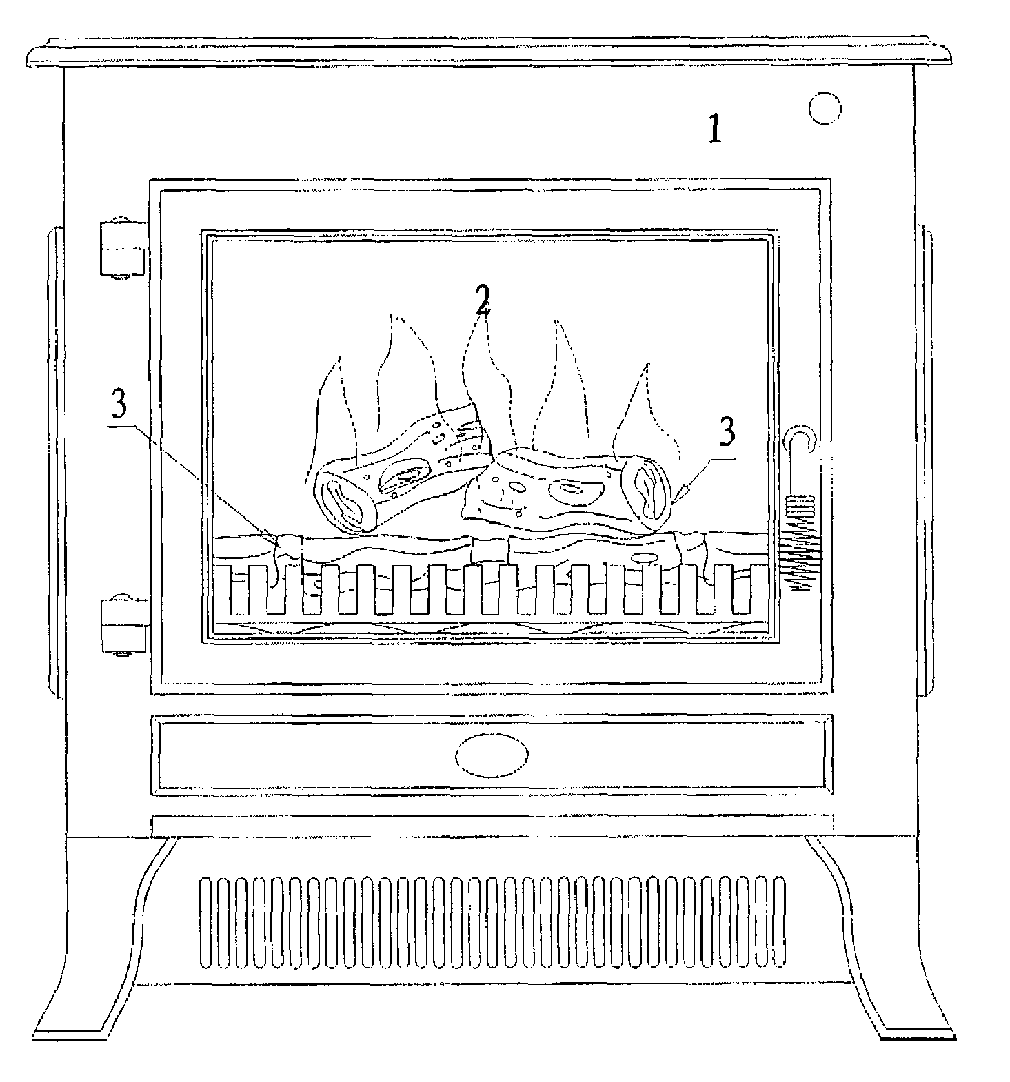
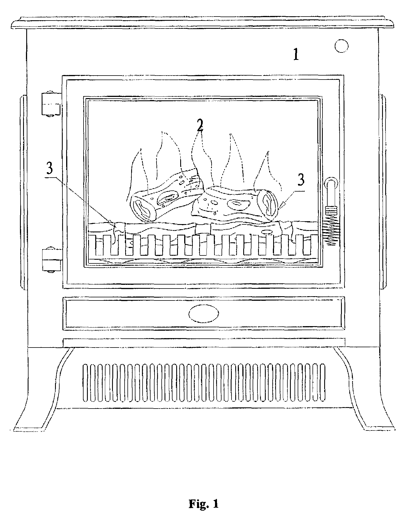
[0020]Referring to FIG. 1 to FIG. 3, the invention relates to an electric fireplace with a flame simulating assembly, comprising: simulated charcoal 3, light source for simulated charcoal 8, the electric heating fitting 10 and flame simulating assembly. The flame simulating assembly includes dynamic light source 6, light filter screen 4 and the glass wall with a mirror surface 7. This dynamic light source 6 includes the fixed light source 12 and photic cover 15 which is composed of three active centrifugal blades 151. The light filter screen 4 is made of plastic or organic glass slice treated by spraying or printing in order to obtain translucency and filter effect. Furthermore, there are m...


PUM


Abstract

An electric fireplace having a fire simulating assembly is provided. The fire simulating assembly includes a semitransparent light filter screen, a mirror glass wall and a dynamic light source. The dynamic light source includes fixed light source and a photic cover composed with many rotating centrifugal blades. There are many photic apertures in flame shape. The centrifugal blades rotate around a center of the light source. There are clearances between the centrifugal blades causing light to reflect through the centrifugal blades. The electric fireplace achieves a natural effect of vivid, rising and leaping simulated flame.

Description

FIELD OF THE INVENTION[0001]The present invention relates to an electric fireplace, in particular, relates to an electric fireplace having a fire simulating assembly.BACKGROUND OF THE INVENTION[0002]Heating is necessary for the human being from ancient time. People warm themselves by burning branches of trees since the invention of how to make fire. With the increasing of living standard, electric fireplace has been one of the popular heating means.[0003]The means of electric heating in existence have two categories: the heater only supplying warm and the electric fireplace having both flame vision and warming function. The latter is an electric fireplace unit having a fire simulating assembly to simulate flame vision. The fire simulating assembly is generally divided into two categories. The first kind of the assembly is a simulating combustion medium such as coal or burning branches. Such combustion medium is usually substituted by plastic house with branch shape and color on its ...

Claims


Application Information

Patent Timeline
Patent Type & Authority Patents(United States)
IPC IPC(8): G09F19/00B60Q1/14F21S4/00F24B1/18G09F13/00F21S10/04F23C1/00F24C7/00F24D13/02
CPCF24C7/004
Inventor CHEN, JIANMING
Owner CHEN YUEPENG
Learn More