
Drying machine

a drying machine and drying technology, applied in drying machines, lighting and heating apparatus, furnaces, etc., can solve the problems of increasing the amount of energy consumed to dry the matter to be dried, increasing the energy cost, and reducing the drying effect of the drying machine, so as to prevent the disadvantage

Inactive Publication Date: 2008-01-29
SANYO ELECTRIC CO LTD +1
View PDF10 Cites 17 Cited by
  • Summary
  • Abstract
  • Description
  • Claims
  • Application Information

AI Technical Summary

Benefits of technology

[0007]According to the first invention, while a high pressure can be adapted to a targeted value lower than a value during a normal operation, a decrease in cooling capacity due to a decrease in a refrigerant circulation amount can be compensated, thereby making it possible to lower the temperature of air discharged to the storage chamber while ensuring a predetermined cooling capacity in the evaporator. This allows delicate drying, and a reduction can be made in burdens on the matter to be dried during drying.
[0009]According to the second invention, while a high pressure can be adapted to a targeted value lower than a value during a normal operation, a decrease in cooling capacity due to a decrease in a refrigerant circulation amount can be compensated, thereby making it possible to lower the temperature of air discharged to the storage chamber while ensuring a predetermined cooling capacity in the evaporator. This allows delicate drying, and a reduction can be made in burdens on the matter to be dried during drying.
[0011]According to the third invention, in addition to the inventions described above, a discharged heat amount can be easily and accurately controlled.
[0013]According to the fourth invention, in addition to the inventions described above, it is possible to secure a recovery efficiency of a washing liquid in the evaporator.
[0015]According to the fifth invention, in addition to the inventions described above, it is possible to effectively prevent a disadvantage that an abnormal increase is caused in a discharged refrigerant temperature of the compressor due to an insufficient discharged heat amount immediately after the cool-down mode is started.
[0016]This allows longer lives of devices constituting the heat pump, and also allows elimination of a disadvantage that the compressor stops protection.

Problems solved by technology

However, in the drying machine using such an electric heater or gas burning heater, as low-temperature humid air outside the storage chamber is used for the high-temperature air sent into the storage chamber, a long time is required until the matter to be dried dries.
Therefore, an energy consumption amount to dry the matter to be dried is increased, leading to a problem of increased energy costs such as an electric bill and a gas bill.
Such a matter to be dried is easily damaged by hot air during the drying operation, and it is therefore necessary to lower temperature of the hot air discharged into the storage chamber during the drying operation.
However, in such a case, a pressure increases on a low-pressure side due to a pressure drop caused on a high-pressure side of a refrigerant circuit configured in the heat pump, thus leading to an increase in a refrigerant evaporation temperature of an evaporator.
This causes a problem that it is not possible to sufficiently cool down the air from the storage chamber which exchanges heat with the evaporator, and the moisture evaporated from the matter to be dried cannot be condensed and removed.
Particularly, in a dry cleaner using a petroleum-based solvent as a cleaning fluid, there are problems that the solvent cannot be sufficiently recovered, that a rate of recovering the solvent decreases, and that a running cost is increased due to an increase in an amount of added solvent.

Method used


Image

  • Drying machine
  • Drying machine
  • Drying machine

Examples


Embodiment Construction

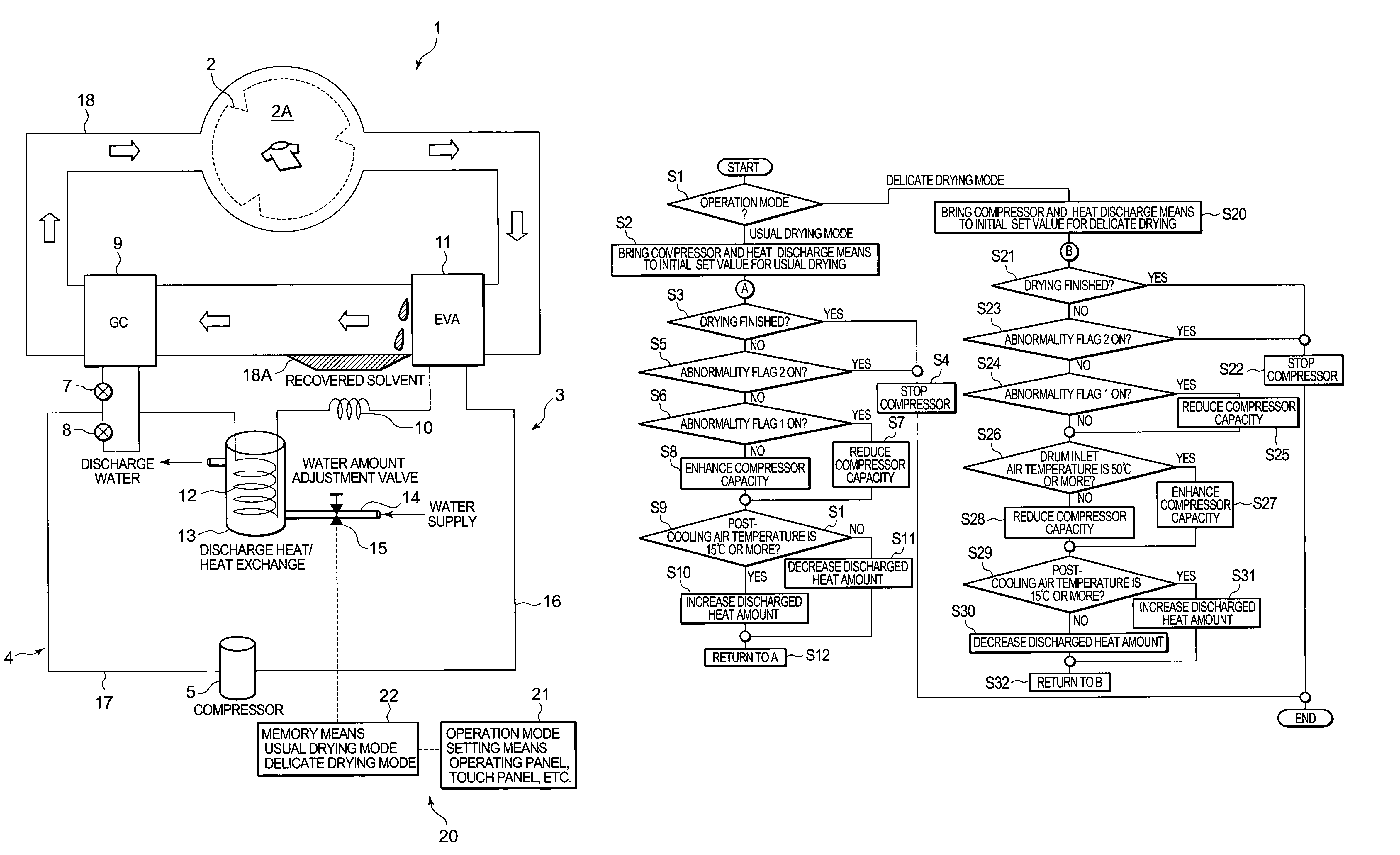
[0029]The present invention has been attained to solve conventional technical problems, and provides a drying machine which achieves delicate drying and which can reduce burdens on a matter to be dried during drying while ensuring a predetermined evaporation temperature in an evaporator. Embodiments of the present invention will hereinafter be described in detail with reference to the drawings.

[0030]FIG. 1 shows a schematic constitution diagram of a dry cleaner 1 using, for example, a petroleum-based solvent as a cleaning fluid, in one embodiment of the drier to which the present invention is applied. In the drawing, 2 denotes a cylindrical drum including a large number of through holes formed in a peripheral wall, and clothing is washed with a washing liquid in a storage chamber 2A of the drum 2 and subsequent drying is also performed therein. This drum 2 is rotated by an unshown drum motor, for example, at a speed of 30 to 50 rpm.

[0031]Moreover, there is connected, to the drum 2, ...


PUM


Abstract

An object is to provide a drying machine which can accomplish delicate drying and reduce burdens on a matter to be dried during drying while securing a predetermined evaporation temperature in an evaporator. In summary, a dry cleaner equipped with a heat pump device comprises a water-cooling heat exchanger which removes heat from a refrigerant entering a capillary tube; and a control device which variably controls a discharged heat amount in the water-cooling heat exchanger and capacity of the compressor, wherein the control device has at least two kinds of drying modes including a usual drying mode and a delicate drying mode, and in the delicate drying mode, a temperature of air discharged into a storage chamber is set lower than in the usual drying mode to control the capacity of the compressor and to increase the discharged heat amount in the water-cooling heat exchanger.

Description

BACKGROUND OF THE INVENTION[0001]The present invention relates to a drying machine which comprises a storage chamber to store a matter to be dried and which executes a drying operation for the matter to be dried in the storage chamber.[0002]In such a drying machine, an electric heater or a gas burning heater has heretofore been used as a heat source. After heating outside air by the electric heater or the burning heater to produce high-temperature air, the air is blown into a storage chamber in which the matter to be dried is stored to thereby dry the matter to be dried in the storage chamber. Moreover, the high-temperature air in the storage chamber, which has dried the matter to be dried, is discharged to the outside.[0003]However, in the drying machine using such an electric heater or gas burning heater, as low-temperature humid air outside the storage chamber is used for the high-temperature air sent into the storage chamber, a long time is required until the matter to be dried ...

Claims


Application Information

Patent Timeline
Patent Type & Authority Patents(United States)
IPC IPC(8): F26B21/06
CPCD06F43/086D06F58/206
Inventor TADANO, MASAYAMASUDA, TETSUYANAKAMURA, TAKAHIRONISHINO, MASAFUMIASADA, NOBUHIRONAGANAWA, MITSURU
Owner SANYO ELECTRIC CO LTD
Learn More