
Analog-to-digital converter and semiconductor device

a technology of analog-to-digital converters and semiconductor devices, applied in the field of analog-to-digital converters, can solve problems such as the negative effect of ad conversion

Active Publication Date: 2008-01-22
SONY CORP
View PDF9 Cites 99 Cited by
  • Summary
  • Abstract
  • Description
  • Claims
  • Application Information

AI Technical Summary

Benefits of technology

The present invention provides an analog-to-digital converter, semiconductor device, and electronic apparatus that can avoid the adverse effect of noise generated in a voltage comparator on the operation of other voltage comparators. This is achieved by using a reference signal generator to generate a reference signal and a comparator to compare the reference signal with a signal transmitted from an effective region. A counter counts the reference signal and holds a count value at the time of completion of comparison. A reference signal supply interface unit supplies the reference signal to multiple comparators via different signal lines. This results in improved accuracy and reliability of the analog-to-digital conversion process.

Problems solved by technology

As a result, an adverse effect is exerted on AD conversion.

Method used


Image

  • Analog-to-digital converter and semiconductor device
  • Analog-to-digital converter and semiconductor device
  • Analog-to-digital converter and semiconductor device

Examples


first embodiment

Buffer Circuit (First Embodiment)

[0193]FIG. 10 is a diagram showing, together with a detailed example of the configuration of the voltage comparator 252, a detailed example of the configuration of the buffer circuit 280 according to the first embodiment. FIG. 11 is a diagram showing, together with a detailed example of the configuration of the voltage comparator 252, a detailed example of the configuration of a known buffer circuit 280 serving as a comparison example.

[0194]The buffer circuit 280 is a source follower circuit. Specifically, the buffer circuit 280 includes an NMOS transistor (referred to as an “amplifying transistor”) 282, which is connected at its drain to the power supply Vdd and which receives at its gate the reference signal RAMP via the reference signal line 251, and an NMOS transistor (referred to as a “load MOS transistor”) 284, which is connected between the source of the amplifying transistor 282 and the ground and which supplies the operating current to the a...

second embodiment

Reference Signal Supply IF Unit (Second Embodiment)

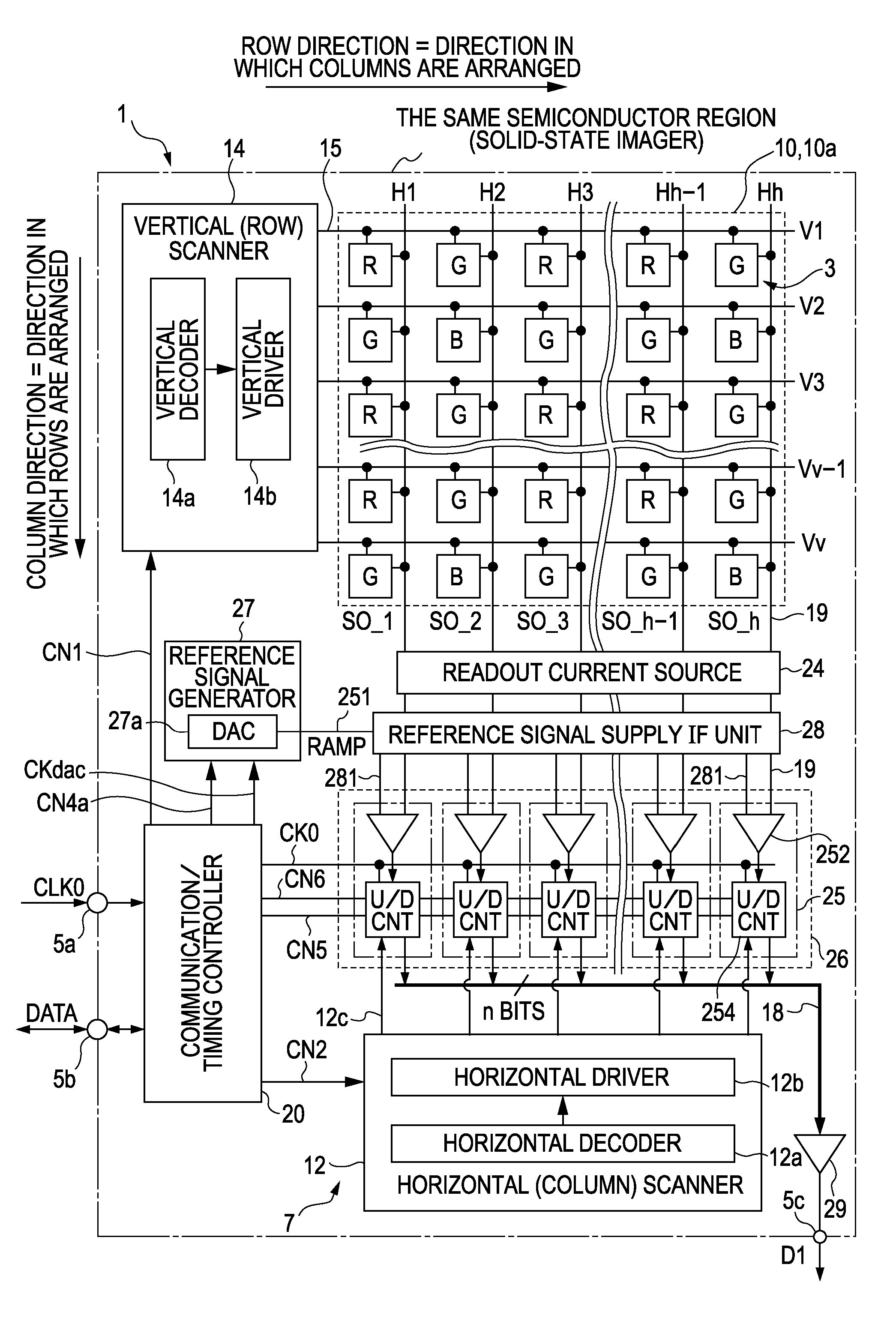
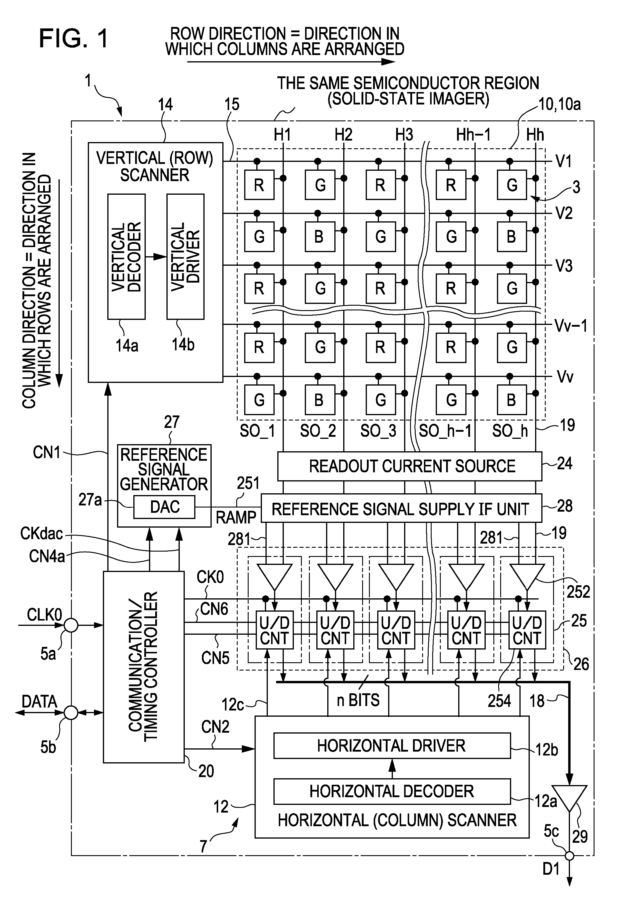
[0207]FIGS. 14 and 15 are diagrams showing the reference signal supply IF unit 28 according to the second embodiment. In particular, the signal transmission (interface) among the unit pixels 3, the reference signal generator 27, and the voltage comparators 252 included in the column AD circuits 25 will be examined. FIG. 14 shows the basic configuration of an interface for use in the second embodiment. FIG. 15 shows the overall outline of the interface.

[0208]In the reference signal supply IF unit 28 according to the first embodiment, with the reference-signal-input-stage-separated configuration in which the reference signal input stages of the voltage comparators 252 are separated into a plurality of blocks, one block includes one buffer circuit 280 and a plurality of voltage comparators 252. In other words, the number of voltage comparators 252 covered by one buffer circuit 280 is plural. In contrast, in the second embodiment, one b...


PUM


Abstract

An electronic apparatus includes a CMOS image sensor and a signal processor operable to process an output signal from the CMOS image sensor. The CMOS image sensor includes the following elements: an imaging region; a reference signal generator operable to generate a reference signal; a comparator operable to compare the reference signal generated by the reference signal generator with a signal transmitted from the imaging region; a counter operable to count, in parallel with comparison performed by the comparator, a predetermined count clock and to hold a count value at the time of completion of comparison performed by the comparator; and a reference signal supply interface unit operable to supply the reference signal generated by the reference signal generator to a plurality of comparators via different signal lines, respectively.

Description

CROSS REFERENCES TO RELATED APPLICATIONS[0001]The present invention contains subject matter related to Japanese Patent Application JP 2005-197044 filed in the Japanese Patent Office on Jul. 6, 2005, the entire contents of which are incorporated herein by reference.BACKGROUND OF THE INVENTION[0002]1. Field of the Invention[0003]The present invention relates to analog-to-digital (AD) converters (abbreviated “ADC”) and semiconductor devices, such as imagers, provided with the ADCs. More particularly, the present invention relates to the mechanism of so-called single-slope-integration or ramp-compare AD conversion for comparing a reference signal that changes with a predetermined slope with an analog signal to be processed and counting the comparison time.[0004]2. Description of the Related Art[0005]In electronic apparatuses, such as cameras, cellular phones, and imaging modules, various ADCs for converting an analog signal into a digital signal are used.[0006]For example, physical-quan...

Claims


Application Information

Patent Timeline
Patent Type & Authority Patents(United States)
IPC IPC(8): H03M1/34H03M1/08H03M1/56H04N25/00
CPCH03M1/0607H03M1/08H04N5/378H04N5/3742H04N5/3745H03M1/123H03M1/56H04N25/767H04N25/77H04N25/616H04N25/78H03M1/12H03M1/68H04N25/75
Inventor TOOYAMA, TAKAYUKISUZUKI, ATSUSHIFUKUSHIMA, NORIYUKIYASUI, YUKIHIRONITTA, YOSHIKAZU
Owner SONY CORP
Learn More