
System for selecting true coincidence events in positron emission tomography

a technology of positron emission tomography and coincidence events, applied in the field of imaging techniques, can solve the problems of reducing detector efficiency, limiting the statistical precision of image reconstruction, and reducing the number of photons, so as to improve the ability to select data, enhance the selection of true (t), and improve the sensitivity and/or resolution of a pet scanner

Inactive Publication Date: 2008-01-22
ADVANCED APPLIED PHYSICS SOLUTIONS
View PDF8 Cites 12 Cited by
  • Summary
  • Abstract
  • Description
  • Claims
  • Application Information

AI Technical Summary

Benefits of technology

"The patent describes new methods for improving the sensitivity and resolution of PET scanners by enhancing the selection of true annihilation events relative to true scattered and random events. This is achieved by reconstructing Compton scattering interactions and utilizing γ-ray polarization effects associated with positron annihilation and Compton scattering. These methods provide a better ability to select data corresponding to true events while simultaneously suppressing data corresponding to scattered and random events during PET applications."

Problems solved by technology

Improvements in the design of the scintillation crystals and / or photodetectors can improve the spatial resolution, but are limited by an intrinsic spatial resolution that can not be less than one half of the width of the discrete scintillation crystals utilized in the detector.
A significant limitation of such designs is the substantial reduction in the number of photons that traverse the “pinhole,” thereby reducing detector efficiency.
Detection and accumulation of these “false” coincidences limit the statistical precision of image reconstruction.
Although a number of elaborate techniques and algorithms have been developed in an effort to mitigate the effects of the noise on PET images, TS and R noise issues remain and continue to limit the resolution and precision of the resulting PET images.

Method used


Image

  • System for selecting true coincidence events in positron emission tomography
  • System for selecting true coincidence events in positron emission tomography
  • System for selecting true coincidence events in positron emission tomography

Examples


Embodiment Construction

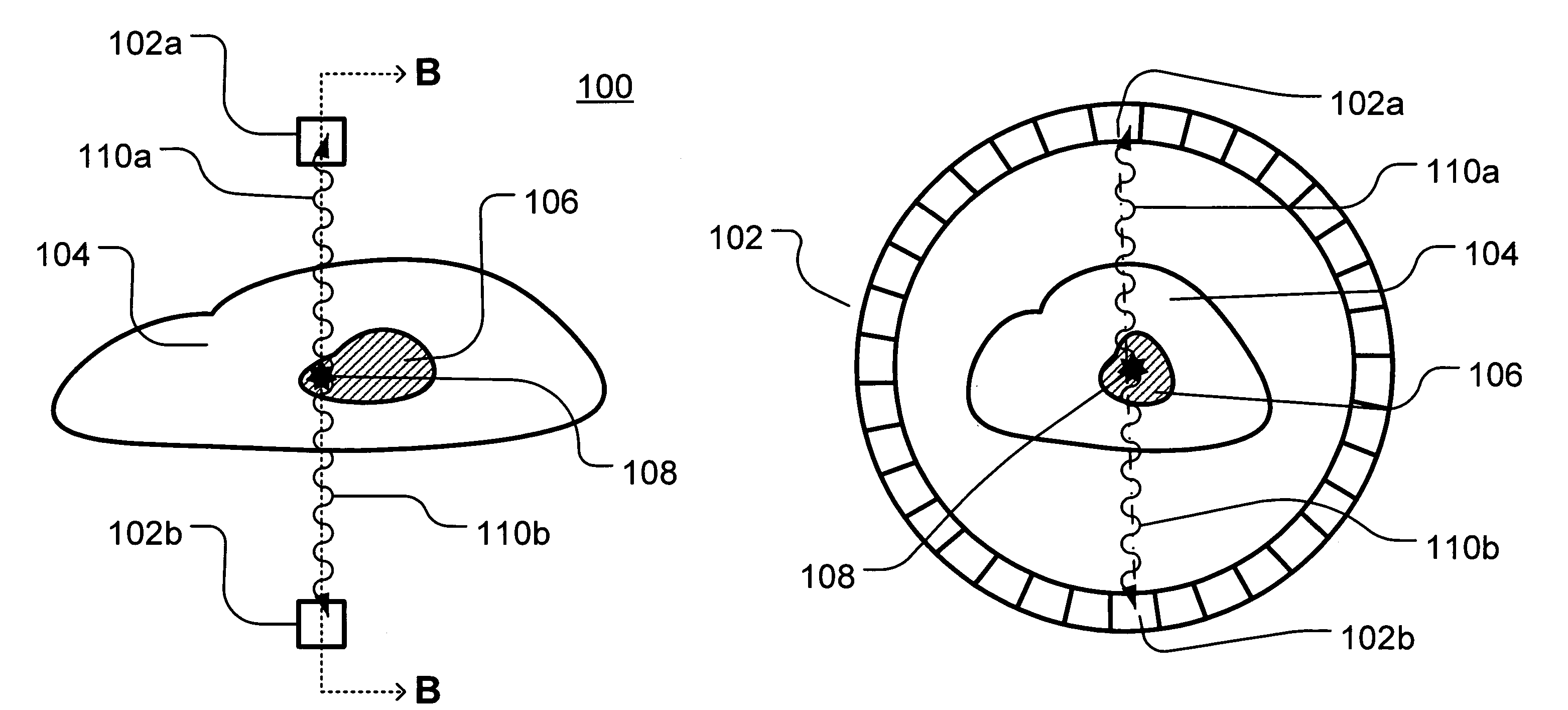
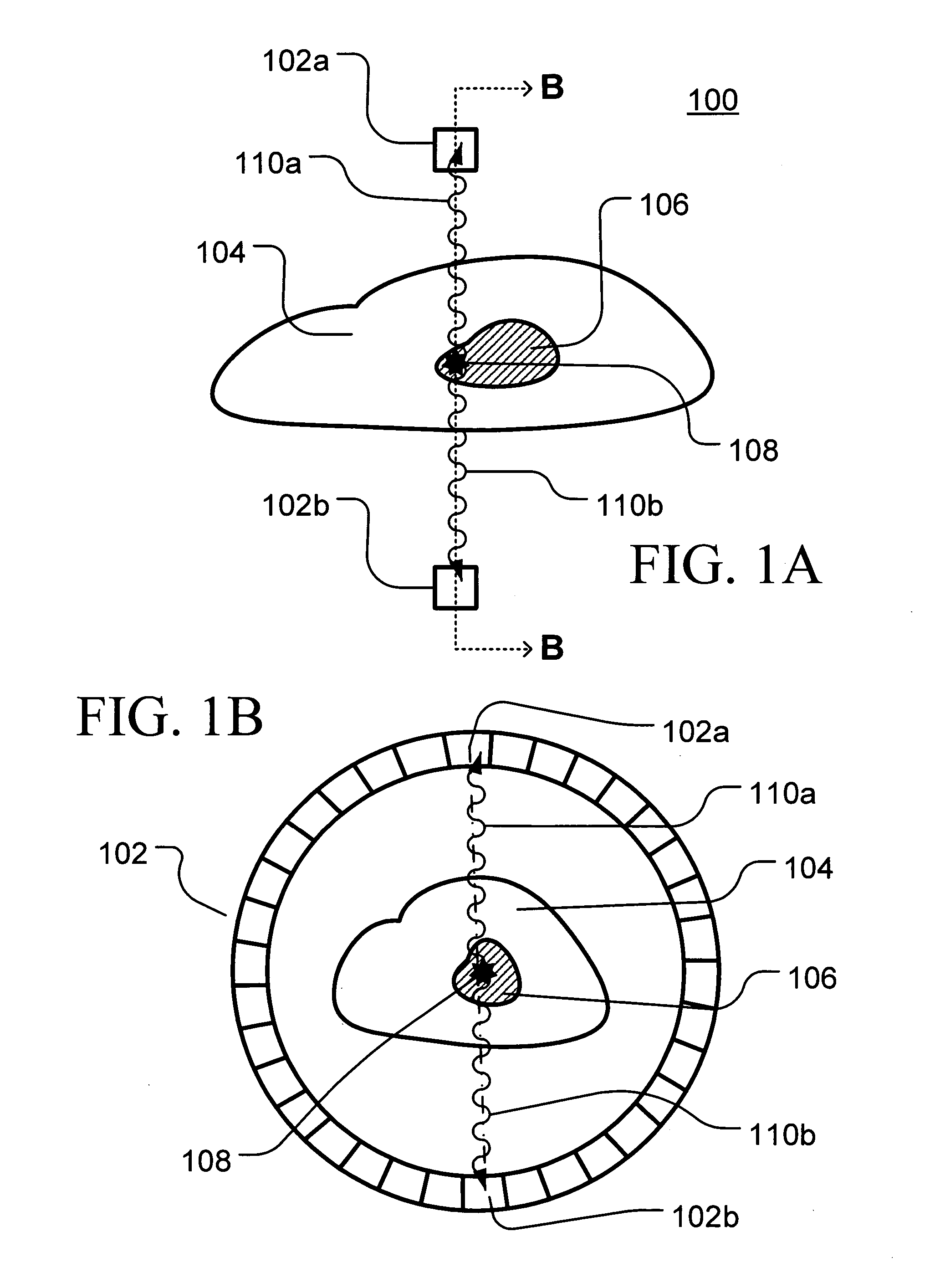
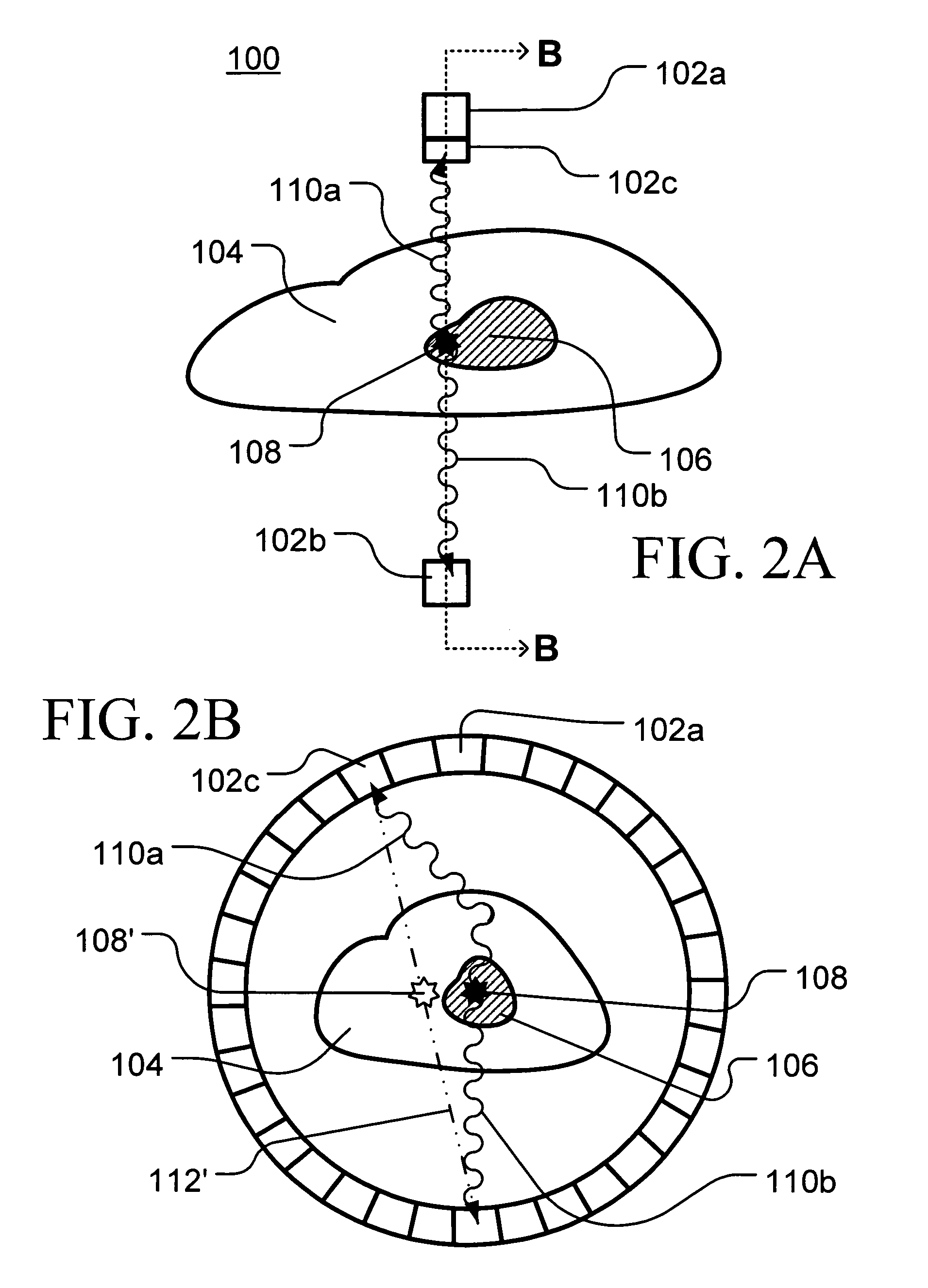
[0018]Example embodiments of the invention will now be described more fully hereinafter with reference to the accompanying drawings, in which example embodiments of methods according to the invention are shown. Those of ordinary skill in the art will, however, appreciate that this invention may be embodied in many different forms and should not be construed as being limited to the example embodiments illustrated and described herein. Rather, these example embodiments are provided so that this disclosure will be thorough and complete, and will fully convey the scope of the invention to those skilled in the art. Identical or related reference numerals and designations are used throughout the specification and drawings to identify identical and / or corresponding elements of the illustrated structures.

Compton Cameras

[0019]Conventional Compton cameras 200, as generally illustrated in FIG. 4, include first 206 and second 208 detectors arranged on the same side of an imaging area 202 in whi...


PUM


Abstract

Provided are new methods for enhancing the selection of true (T) annihilation events relative to the inclusion of true scattered (TS) and random (R) annihilation events in PET tomographs and thereby improving the sensitivity and / or resolution of PET scanners. The methods include reconstruction of Compton scattering interactions in the γ-ray detectors for determining the angles of incidence of the γ-rays received at the detectors and may utilize γ-ray polarization effects and electron recoil data associated with positron annihilation and Compton scattering. The use of the γ-ray polarization effects provides an improved ability for selecting data corresponding to T events while simultaneously suppressing data corresponding to TS and R events during PET applications.

Description

PRIORITY STATEMENT[0001]This application claims priority under 35 U.S.C. § 119 from U.S. Provisional Application No. 60 / 631,881, filed Dec. 1, 2004, the disclosure of which is incorporated herein by reference in its entirety as if set forth fully herein.BACKGROUND OF THE INVENTION[0002]Positron Emission Tomography (“PET”) is an imaging technique that can be used to develop two-dimensional and three-dimensional tomographic images of a distribution of positron-emitting isotopes within a subject, such as a human patient undergoing medical imaging in which the resulting PET images provide a visual depiction of tissue differences within the subject. PET procedures typically involve introducing one or more radiolabeled pharmaceutical tracer compounds into the subject, usually through injection or inhalation. As the radioisotope(s) incorporated in the pharmaceutical tracer compound decays, it releases positrons. These positrons collide with surrounding matter before combining with an elect...

Claims


Application Information

Patent Timeline
Patent Type & Authority Patents(United States)
IPC IPC(8): G01T1/164G01T1/166
CPCG01T1/172G01T1/249G01T1/164G01T1/161
Inventor BRYMAN, DOUGLAS
Owner ADVANCED APPLIED PHYSICS SOLUTIONS
Learn More